vol.2
Forum Replies Created
- AuthorPosts
-
Ok. Great. So maybe that means I did good by purchasing the parts unit with the correct transformer.
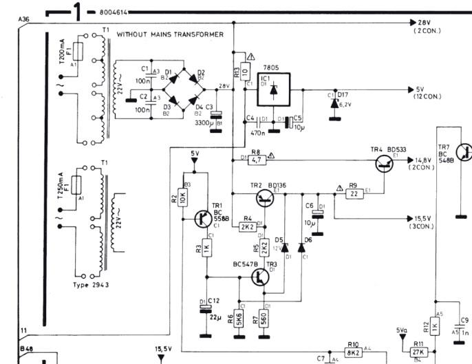
It seems like I should be able to drop in the 2943 (120V version) into the space where the 2941 (220V version) is, and the rest of the circuit will be happy.
Would you agree with that assessment?
Thanks
I went ahead and bought a broken unit because I thought I would have to swap the transformer out. ? It wasn’t very expensive, but I feel kinda stupid now.
Is that what’s going on here then? In the top configuration, the middle two taps on the device side legs are also going to ground, but on the bottom the middle two taps are no connection? I believe that my current configuration looks like the top one, so does that mean I have to cut off the 2nd and 5th legs of the transformer to get it to work?

Thanks
Ok. I figured it out. I feel silly, but this turned out to be a 220V model. I found this in a secondhand store many years ago and put it in storage as a future project without looking at it too closely. I realized after checking the voltages that I was getting only half the correct voltage on the output of the bridge rectifier.
Is there some way I can swap out the transformer and make this a 120V device?
Thanks
A cracked solder joint, perhaps. Check around the voltage regulators. Martin
Thanks, continuity tests okay on them. Diode test is weird though, I’m going to pull them out and check them.
I’d like to add that I finally got the standby light to appear if I probe around on the board, but it seems to go dim and start blinking after a little while. Perhaps it’s a capacitor, or many capacitors. There’s a lot in here.
Hopefully someone here has a good idea what to check for and can save me some time. I have a feeling that otherwise I’m going to be pulling and checking an awful lot of components.
- AuthorPosts
