Tignum
Forum Replies Created
- AuthorPosts
-
Maybe add a tester to the order! (+ battery) They are cheap, and will give you confidence that the cabling job is good. Regards, J.
I always thought these cabinets were cuts from an extruded profile?
J.
Hi eprokos, two suggestions:
– when you connect the Beolab 18 directly to the Theatre, all is good?
– you could obtain a little tester (as below) to check correct continuity of all connections
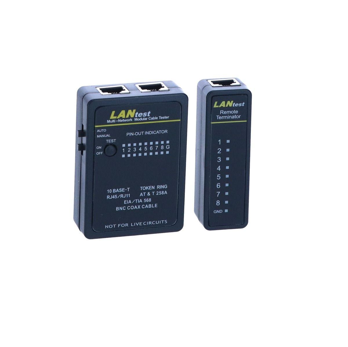
I expect that the colored wires in the Powerlink cable are flexible, and the copper core inside consists of many fine strands. The ABB terminal expects one thick solid copper core inside each wire (as you have with in wall ethernet cables). The little ‘knives’ cut the isolating plastic and ‘bite’ into the solid copper core of ethernet cables. With the flexible wires of the Powerlink cable this might not work so well.
In my home I have the exact same RJ45 terminals: one close to the speaker, one close to the audio device, connected in wall with CAT7 solid core installation cable. Between the terminal and the speaker/audio device, I use a Powerlink cable. Works very well.
Hope this helps, regards, Johan
Hello xschop, with frets I meant the cloth covered plastic speaker fronts. Nothing much to mod there I guess :-). Best of luck, regards, Johan
Hello Eprokos, when used properly, your socket should be good.
Is the white/brown wire not missing on PIN 7? The back of the terminal is missing (here the braided shield is connected to the housing. The braided shield should not be close to where the colored wires are punched in, you risk shorts. Have a look at this: https://www.youtube.com/watch?v=TlU2P12gDso
From the Beolink handbook 1.9, this should be the wiring schedule for PowerLink cabling:

To me it looks like you should carefully redo the wiring. Best is to use solid wire core wires. Between two wall sockets (or patch panels) you can also use good quality standard CAT7 S/FTP wiring in 568-B pinout configuration (see the top color scheme in your socket).
Regards, Johan
Clean job xschop! Did you repaint the metal fronts of the drivers?
I lately refoamed these for a colleague. About time 🙂
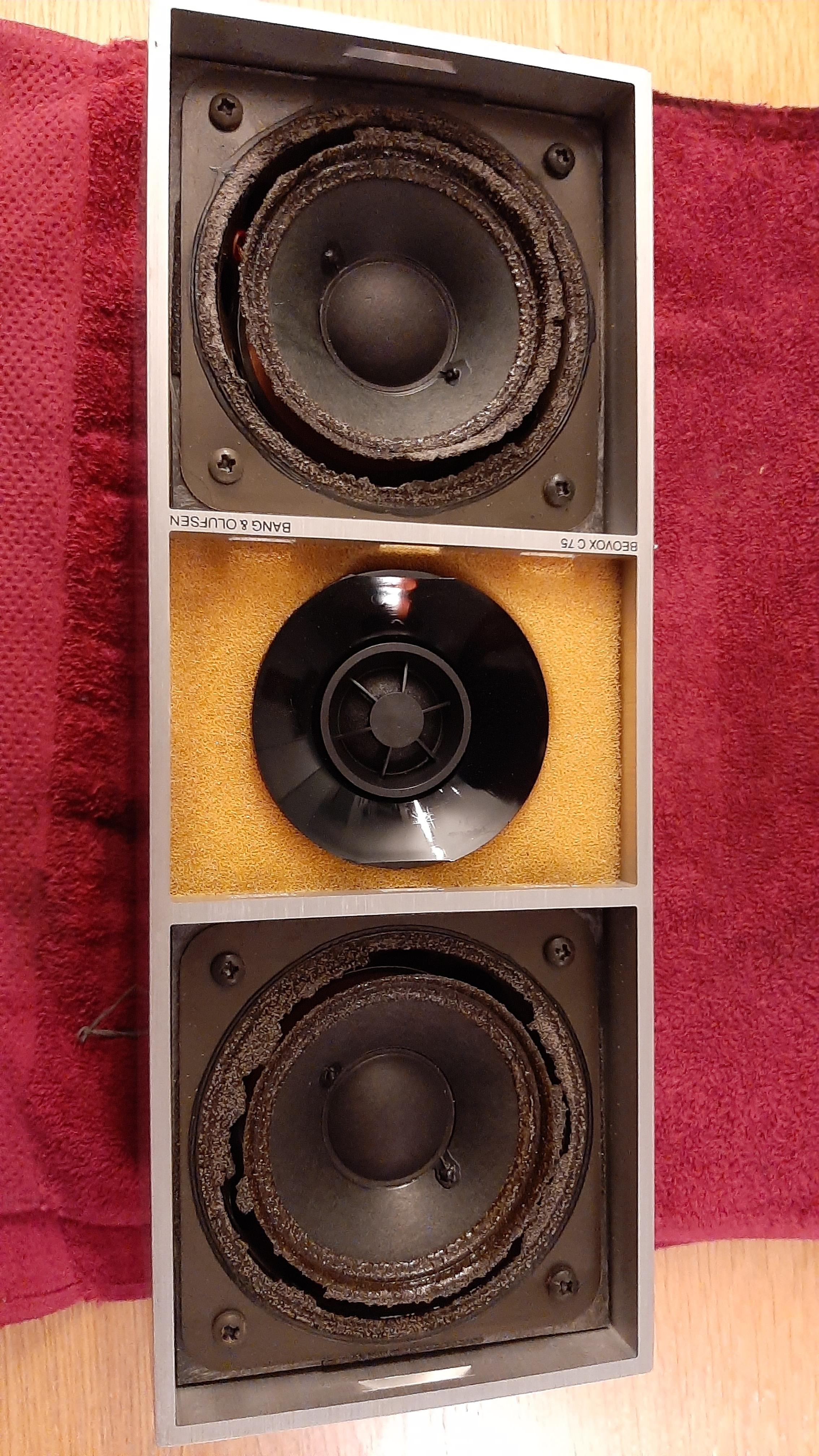
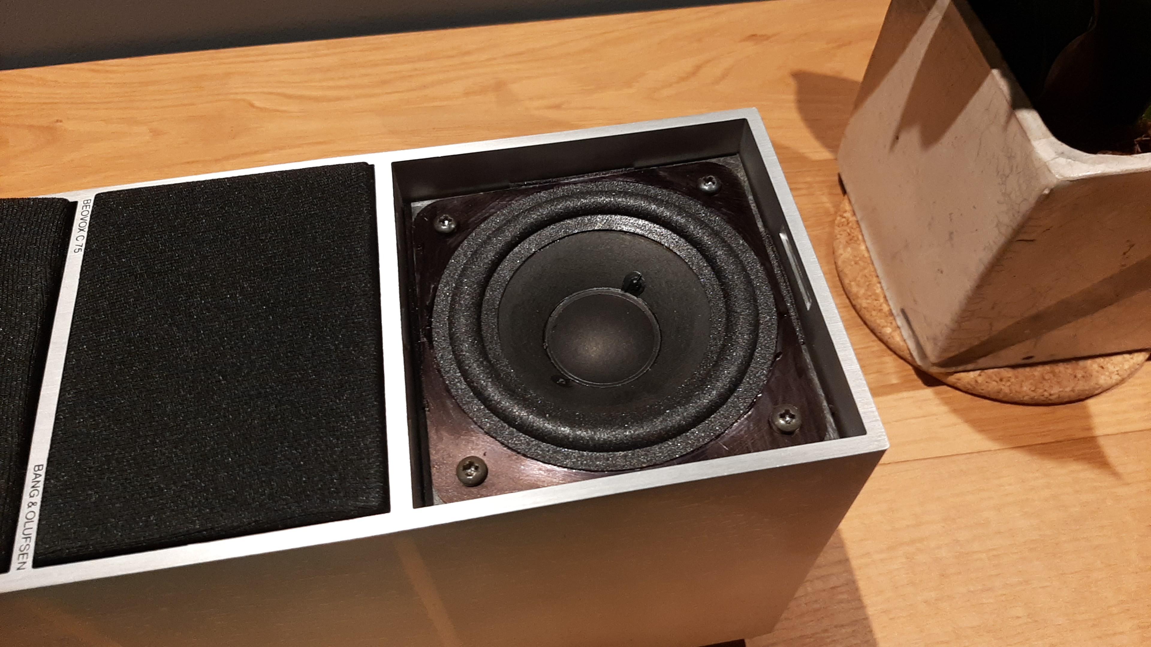
I just touched up the metal of the drivers with a black marker as they will be playing with (freshly washed) frets.
Next issue the sticky black coating []
Hi Madskp, I managed to rub off the sticky coating with methylated spirit (the blue smelly stuff), and found a gloss black paint underneath. My original idea was to have the housing sandblasted and powdercoated, but I abandoned that and am happy enough with the original black (undercoating) paint. Saves quite a bit of (dis)assembly. Maybe worth a try? Regards, Johan
Goed te horen Gertie! En graag gedaan. Fijn dat het naar behoren werkt. Ik hoop dat je nog jaren plezier van de BeoLabs hebt.
Groet, Johan
Hi Madskp,
Is it possible that it has to do with the possibility to ‘rename’ the BeoSound 5’s N.MUSIC to CD or A.MEM? A snip from the BS5 userguide:
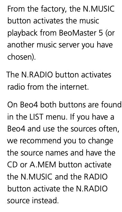
Though you say that it is possible to use CD and RADIO? That would make my suggestion at least inconsistent. Anyway, maybe it helps in finding the answer.
Regards, Johan
I have not read anything in the (quite minimal) manual of the BeoPlay Connection Hub about an “A.OPT 0” or alike. I presume the fixed volume mode is supposed to act somewhat like that. But I like your idea – teaching the Hub the commands of some old random remote controller, to control it separately, and only when needed, while using the TV-controlled headphone volume output. I will give that a try before sticking black tape to the Hub :-). Keep you posted, regards, Johan
Update – all is working… …with some hurdles!
First hurdle – when setting the (older 40″ LED) Samsung to ‘external speakers’, and using an optical Toslink connection, we found an annoyance and a problem: at every volume change request of the remote, the volume gets nicely changed, but on the screen a window opens for some seconds saying something like “You connected external speakers – use the other device to control the volume”. Not great. Furthermore, even when switched to ‘standby’ the Samsung seems to “leak” some optical noise so the Hub (and the Passive) would not turn off after 5 minutes. Also not great.
Next plan – use 3.5mm minijack stereo cable from the headphone socket. I cycled home for this cable (as the original plan was optical of course), but when I plugged it in, the TV went mad. It would hardly react to remote control input and the IR receiver were blinking like crazy! It received ‘volume down’ commands continuously somehow. I checked if no-one was sitting on a remote or something, reset the tv, took the batteries out of any remote in the house, did all kind of checks, and almost bought another TV! (maybe it was good I was on my bicycle, and postponed that moment). All to find in the end (by my brother who came over for (mental) support) that the Apple TV remote (no batteries you can take out) was just frantically sending signals as it got disconnected from the Apple TV (or whatever). That blocked the TV completely! Some googling confirmed this (some people report volume up only!) and a de/re-pairing fixed the issue. I really was thinking that by plugging in the 3.5mm minijack I messed up the electronics of the TV somehow (electric discharge from the Passive through ground or something). Phew – all was good again.
When using the headphone out of a TV (so the volume control is with the TV still), you can set the Hub to fix volume by double pressing the “multi” button at the back. The LED then goes red. You might want to play with the volume setting of the TV and the setting of the Hub to find a comfortable ‘range’.
Some other learning: when you taught the Hub the IR volume (up/down/mute) and you use the headphone out of the TV, make sure that you ‘sync’ the mute statuses of both devices! If not, one of them is in mute alternatively, and you risk having no sound and think there is a much bigger problem :-). I might tape off the Hub IR receiver to avoid this happening.
Hope this is helpful to a future Hub owner!
Regards,
Regards, JohanHello col,
I had this also unfortunately a while ago, with a BR1 BT. I was sent a new keyboard/display unit from my dealer (within the 36 months warranty period).
Regards, Johan
Hi emabonacchi,
jvezina suggested in his post to set the screen to ‘generic’. Will that open the possibility to choose 1920 x 1020? Be careful indeed. Good idea to take photographs of the screen!
Regards, Johan
January 28, 2024 at 8:26 pm in reply to: Speaker Stands (silver/gray) for Beovox S60 Type 6303, U.S., Chicago #29170Hello mjcallo, welcome. That looks really good! Hope you will get the cassette part working again. If you will not find the stands, you could reproduce them maybe, see for instance: https://archivedforum.beoworld.co.uk/forums/t/41952.aspx for inspiration.
Best of luck, Johan
Also have been checking the Service Menu:

But did not find it there either. Could it be because we don’t have a B&O screen connected?
Sorry that I cannot help you any further! Johan
Just tried myself and could not yet find a way to configure to 1920×1080. Will seek some more.
Hello and thanks for your reply. I am doing many and many and many trying from months, buto the problem is not solved. It seems i am not able to find the menu tou suggested. In “Options” i press “red arrow” and go, or “0 0 go”, but i really can not find the “screen configuration”. However, after many and many try, i can tell “EDID emulator” is not the solution. And i can tell the problem source seems to be “Playstation 4” connected to “Dvd source”. U did a “giant work” and i am very frustrating because this seems to be a very stupid setting problem able to destroy all mi job……
Hi emabonacchi, this is the text from the BS3 service manual:

It is important that you only place the ‘cursor’ on ‘OPTION’. Don’t press go yet. ‘OPTION’ only needs to be highlighted, then press the red button and GO. Hope this helps. I will try on my BS3 to reconfirm.
Regards, Johan
Hallo hvb, beter nog, je wordt silver of gold member, en kunt de service manual downloaden van de BeoWorld site!
Succes en groet Johan
For now, this should be it then (using less confusing names):
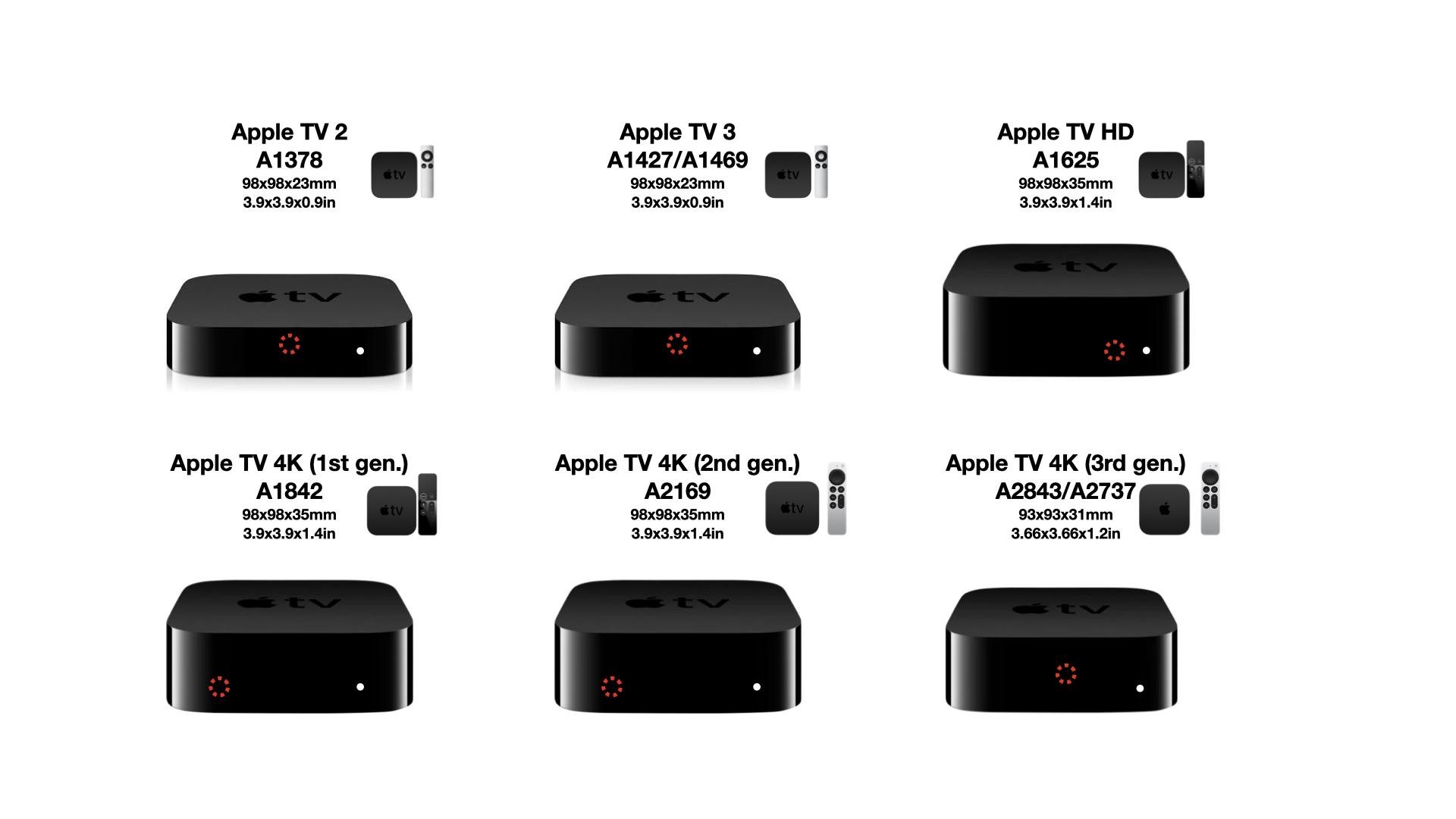
Thanks! I did google a bit more for the IR sensor location of the 2 and 3 and found these (for the 1427):
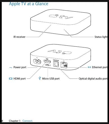
And for “second and third generation”:
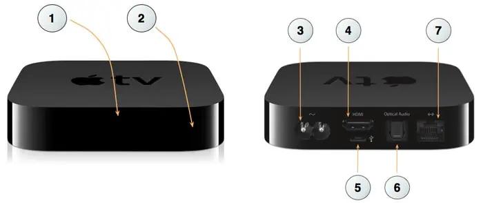
This is different from what I made sofar. Some teardown images (of 2nd gen) confirm center location.
What do you think?
Regards, Johan
- AuthorPosts
