spassmaker
Forum Replies Created
- AuthorPosts
-
Hi
There is no light or LED and really no signs of life on the BM 6000? No cklick?
Watch out your fingers , hope you are skilled for handling with life voltages, electronics and measuring.
Before opening the Beomaster:
!!!FIRST PULL THE MAINS PLUG FROM THE WALL OUTLET !!!!
Noone here in the forum is responsable for what you are doing at home on your own risk.
Sure there are fuses inside.
Exactly 2 of the fuses can be found near the mains transformator on PCB 11 (FUSES AND RELAY)
Download the service manual and you´ll find the right ratings for the fuses depending what mainsvoltage and what type of Beomaster you have.
Regards
Christian
Hi Alf
Voltages that you measured are OK for 33 RPM.
The relay is in off position when 33 is selected.
If you switch to 45 can you hear the relay klicking? With the new one go to next with your ear to the relay.
If 45 is selected the voltage at TR 6 should drop to near zero volt, as the relais should engage.
The relay is switching the resistor networks 1R8 to 1R13
The following part of the circurit is same for both speeds as far as I can see.
A further possible fault could be the caps to the motor 0C6 4700uF and 0C7 150uF BIPOLAR
A hint is mentioned : I’m not sure but the lightbulb 1IL1 is used for the start of wien- bridge, so check if the bulb is OK
Recapping is recommended.
Regards Christian
Hi
Seems that you have to open up the Turntable.
There are 2 screws on the right side to unscrew, then move the tonearm to the middle and fold the top to the left side up, always watching space between tonearm and topplate.
In the back of the topplate you should find a lever wich can be used like the bonnet holder of a car.
In the thread wich i already mentioned you’ll find 2 pictures how it looks original and a few posts later there is a picture how you could repair it wit a screw.
As you are Bronce Member you could download the service manual for further information.
Kind regards
Christian
Hi
Often the transport string is off. Discussed often how to repair with a simple screw.
Looh here for further information:
https://archivedforum.beoworld.co.uk/forums/t/35376.aspx
Kind regards
Christian
Hi
It seems that all signals are present.
If you switch the beocenter on with the remote are the sensorbuttons working as expected?
You could compare the measured signals with the service manual page 7-8.
Pic 1: maybe a different timebase could be OK
Pic 2: ENABLE maybe a different timebase could be OK
Pic 3: KEY DATA seems to be ok
Pic 4: CLP seems to be ok
Did you measure 0 V at IC4 Pin 2 (RESET)?
What happens if you go to testmode by short circuiting the TESTMODE contacts on board 43?
Hi
Sounds like there is a voltage missing somewhere….
Did you check 5 Volt direct on board 42 IC 3 Pin 20, IC2 Pin 16 and IC1 Pin 16?
If you provide an oszilloscope you could measure the CLP signal (Clock Pulse)
which comes from board 40 IC4 Pin 32.
This signal serves several boadrs with the CLP signal.
There should be a straight connection between P52-3 (Board 40) to P63-10 on board 42.
This connection goes straight to IC3 (M5450).
Check onnection for Disp.Data from board 40 P52-2 to board 42 P63-11. to IC 3 Pin 22
Check Key Enable from board 40 P52-6 to board 42 P63-7 (should be low?) to IC 2 Pin 5
BUT:
The MM5450 is just a LED driver IC.
The keys are driven by IC 1, 2 and 4.
Maybe there is a connection lost between board 40 IC 1 Pin 5, 6, 7, 8 via P52- 7, 8,9,10
to board 42 P63- 3, 4, 5, 6 to IC4 Pin 1, 9, 10, 13.
Here to check 5 volt IC 4 on Pin 16
Regards
Christian
Hi Alf
As John mentioned the black wire I remembered that some time ago I had an issue with one of these “Piggyboards”.
The Beogram was playing a record for a time and suddenly turned of, with no STBY Dot.
After deeper investigations it turned out that the Beogram sometimes just turned of completely with no STBY Dot visible. Even while playing or in STBY.
After poking around in the transformer and rectifier section and nothing obvisiously found I determined the small additional board which was implemented for a “saver uPC start” where the black wire, which already mentioned, goes to.
There are only a few parts on it but after changing the transistor and a few parts more the problem was not solved, maybe a carcked trace, I did not find out.
So I decided to extract the board and bring the whole wireing back into the state as the schematic shows.
The main PCB is not changed during the developing.
That did the trick, the Beogram had no dropout anymore and is playing still well.
B&O developer have implemented this board for a better uPC startup, but the older ones still live without that board, so what!?
In my eyes it’s not really necessary respectively I can’t find out.
I can remember that I found some information about the small boards somewhere in the www. but can’t remember where.
Maybe someone has these information and can share this here.
If you are at the end of ideas this would be one more possibility to try.
Regards
Christian
Hi
If you try to connect the remote with your Beosound, the Beosound should blink (maybe one time) to show that the remote is accepted.
If there is no reaction the infrared reciever is dead, common problem here are the caps.
Bit fiddly to get the board out and some soldering skills are recommended.
Here are more information:
Kind regards
Christian
Hi
Cold be a keypad problem, regarding to the SM the \/ button is normaly closed and the /\ button is normaly open.
So as there is a bad contact at the \/ button the tonearm will only stay up as long as you push any other button.
Cleaning the contacts is recommended, look here for further information:
https://beolover.blogspot.com/2017/10/beogram-4004-type-5526-keypad-contact.html
Kind regards
Christian
Reinigen der Laserlinse ist natürlich auch eine gute Idee.
Und wie sieht es mit dem Radio aus?
Stück Draht in die Antennenbuchse stecken und dann sollten da schon einige Sender empfangbar sein.
Tapedeck ist typisch, wahrscheinlich ist der bzw. sind die Riemen hinüber.
Moin John
Deshalb fragte ich:
Treten die Aussetzer nur beim CD Betrieb auf?
Wenn die Aussetzer auftreten, läuft dann die Zeitanzeige oben rechts weiter?
Oder bleibt die Zeitanzeige stehen?
Tritt es mehr am Anfang oder am Ende der CD auf?
Steht die Anlage mit den Boxen auf demselben Regal bzw. Tisch = Vibrationen
Da es sich um das Laufwerk mit dem geraden CD Schlitten handelt kann auch der Laser am Ende sein. Wenn du Glück hast ist es nur der defekte Kondensator im Laserstromkreis
hier C2815 auf der Servoplatine.
Gruß
Christian
Moin Moin
Treten die Aussetzer nur beim CD Betrieb auf?
Wenn die Aussetzer auftreten, läuft dann die Zeitanzeige oben rechts weiter?
Wenn es auch bei Radio und Cassette zu Aussetzernkommt, dann liegt es häufig am Muting Relais, welches die Lautsprecher abschaltet.
Das Beocenter hat ein weiteres paar Lautsprecherausgänge, welche nicht über das Relais laufen, einfach einmal umstecken und ausprobieren.
Gruß
Christian
Hi Graham
Am I right that the tonearm is “tracking” in Play mode?
If the tonearm travels not to the home position there seems to be a error in the motor driver stage.
here to check transistors:
TR 26, 27, 28, 29, for FF and tracking forward
TR 30, 31, 32, 33 for FR and “tracking backwards”
These are the drivers for the motor in “play mode”.
Tracking is activated via 0R3 and =0R4, means if the leavespring contact is not engaged (OPEN) by the solenoid, there is no tracking possible because there is no voltage (around 20 to 24 V) at 0R3 and 0R4.
Hope I’m right, if not let me know:
As I remember, there should be a tracking function in both directions (0R2 and 0R3) so when in “Play” mode try carefully pushing the toneearm to the right direction the tracking motor should work.
FF and FR is independent from this leavespring switch, as the arm should travel when you press STOP, FF or FR while the solenoid is deengaged.
FF and FR is activated by the switches in the pushbuttonboard (BOARD 4) via TR 25 and TR 34 on BOARD 1.
As no return with STOP or FR is possible I would search the mentioned transistors TR 34, 30, 31, 32, 33 for shorts or open.
Had quiet often damaged transistors in the driver stage.
Kind regards
Christian
Hi
Just one question
Did you use a new relay or a used one?
Regards
Christian
- Hi
If the wooden surround is still in place on the metal frame you could easyly put a new wood veneer trim on it like this:
https://www.ebay.de/itm/264966647721 (google search)
I’m not the seller or something like this.
This veneer has a paper laminatet backside, is easy to cut with a sharp knife.
As glue you could use a kontact cement like Pat..x.
Sanding the edges with 180 -320 grid.
Spray with semi matte clear coat and enjoy the new look.
Regards
Christian

Hi
Didn’t heard about a special antistatic coating, indeed the original coating is very fragile, never use rough cleaning tools like scotch sponges .
I’ve used a thin layer 2 K clear coat wich is more resistant against scratches and touching.
Had never any problems with static on vinyl.
Regards
Christian
- As you removed the ribs the platter will loose,about 1 to 2 mm height.
- Tage some ( maybe 6 around the outer edge of the subplatter) felt pads to raise to desired heisst.
Hi
Trolle some different sandingpaper, or some Kind of sanding wool like this:
to get a smooth surface.
And try different speeds of the Drill
For clear coat take matte finish
Regards Christian
Hi
I have had a similar problem with a platter from a beogram 4xxx, sad I can´t remember which model it was.
The subplatter (where the belts runs) was not glued to the top aluminium platter with the ribs, there are some models with this seperated platters.
So the ribs are inserted from the top of the aluminium platter and melted to a nearly flat stucture at the backside of the aluminium platter.
There I cutted this melted part away and pried the the ribs out from the backside.
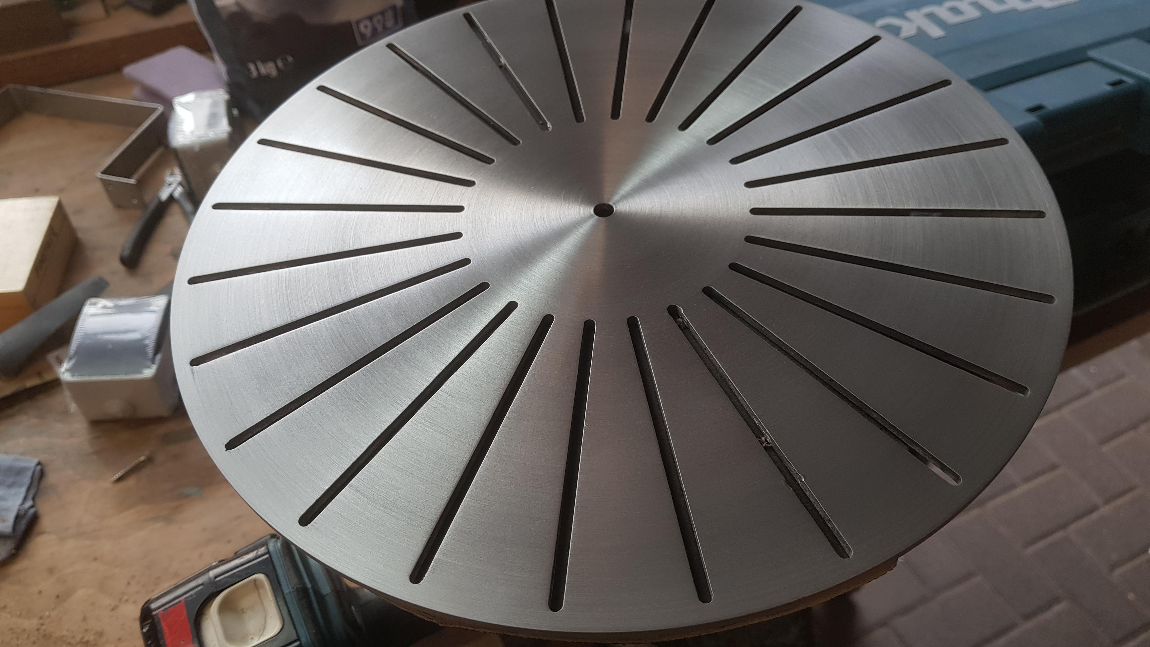
I sanded the platter with some 600 -800 grain paper on a cordless drill with an attached woodplate where I could fix the aluminium platter with two countersunk srews. The screws will make a little mark at the holes for the ribs but the ribs are covering this mark if you tighten the screws not to hard.
Here is a picture of the sanded platter, sadly I took only one picture

After sanding I gave it layer of clear coat and pushed back the ribs in.
They are pressed fitted and must not be glued in place again.
Watch out before how the ribs are mounted there is and out- and inside.
So the only thing that is needed is a way to seperate the subplatter from the alumium platter…maybe hot water woul help, I don´t know.
I wish you good luck!
Kind regards
Christian
- AuthorPosts
