pilatomic
Forum Replies Created
- AuthorPosts
-
@Pilatomic: thnx! This sounds really helpful. One question. Is it correct that the +/-35v at the C5 capacitor is always available? So also when the BeoLab 6000 is in stand-by/Red LED on?
The voltage across C35 will only be present when the LB6000 is turned on. ( Relay RL1 closed )
If you need a permanent voltage, you can find it across C31. It will probably have quite a lot of ripple, but the DC/DC converter should be able to deliver a stable output voltage nonetheless.Hi KolfMAKER,
I checked out the schematic you posted, and at first the circuit around the 5V point was not make any sense. I believe it is rather a 34.5V point ! ( A2 and A5 are definitely 8.6V and -8.6V according to this schematic )
IMHO, your best option is to use the +35V present across the C5 capacitor ( it is the leftmost large red circle on the drawing ). You can find the negative side ( 0V ) by identifying the large white band on the capacitor.
Then use an isolated DC/DC to get a clean isolated 5V (you don’t technically need an isolated supply, but it makes things a lot easier to avoid noise and some issues with different reference potentials).
I would recommend the TMR 4-4811WI, as it accepts inputs from 18 to 75V.
Last advice : You might want to find a bluetooth module with a good quality audio output. Many of them are sub par, and would probably sound like a disappointment on those speakers.
Best luck with your project !
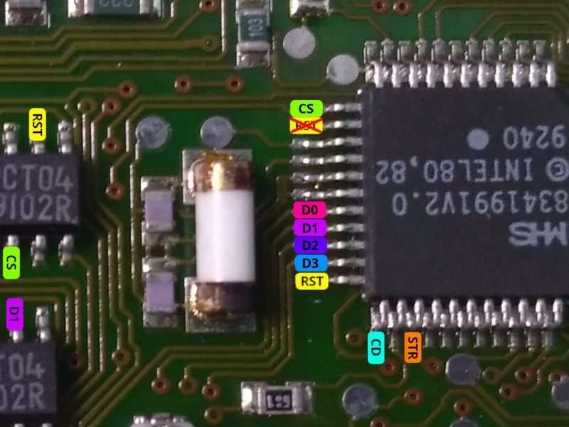
ERRATUM : Bad wiring diagram in installation manual.
There was a mistake in the section 6, about the signals connections on the MHS CPU. The RST pin was incorrectly placed.
I apologize for this mistake !
If you ran a jumper wire to the wrong pin in an attempt to make the connection according to this diagram, it does not seem to cause any issue, but it is better to remove it.
The installation manual v1.1 contains the correct diagram.

- AuthorPosts
