pilatomic
Forum Replies Created
- AuthorPosts
-
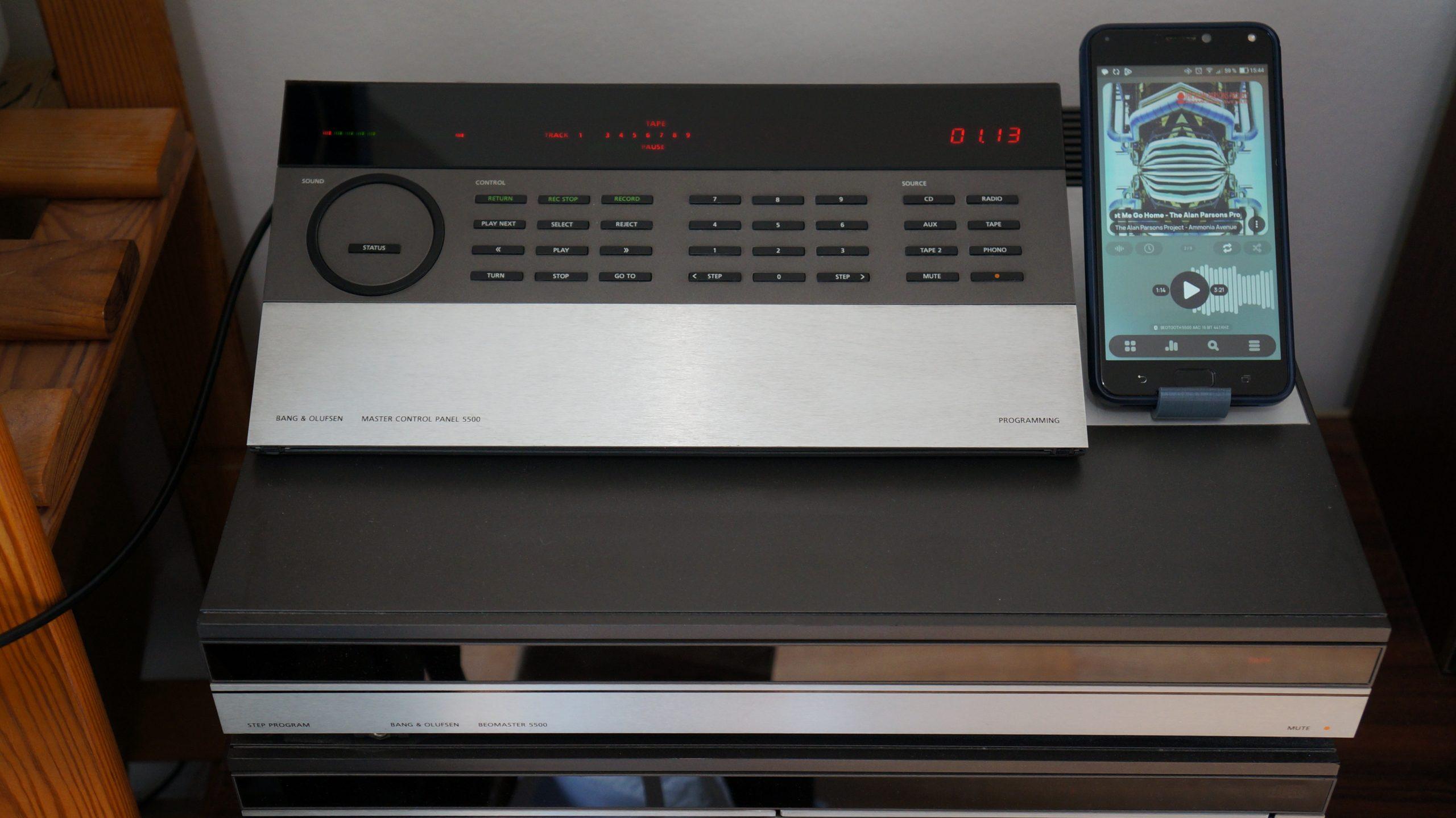
(Is the MCP showing the elapsed time of the playing source? – they are only one second apart)
Well observed ! The slight difference is due to the playing app on the phone, and unrelated to my project.
I’ll open a new thread soon with all the details 😉
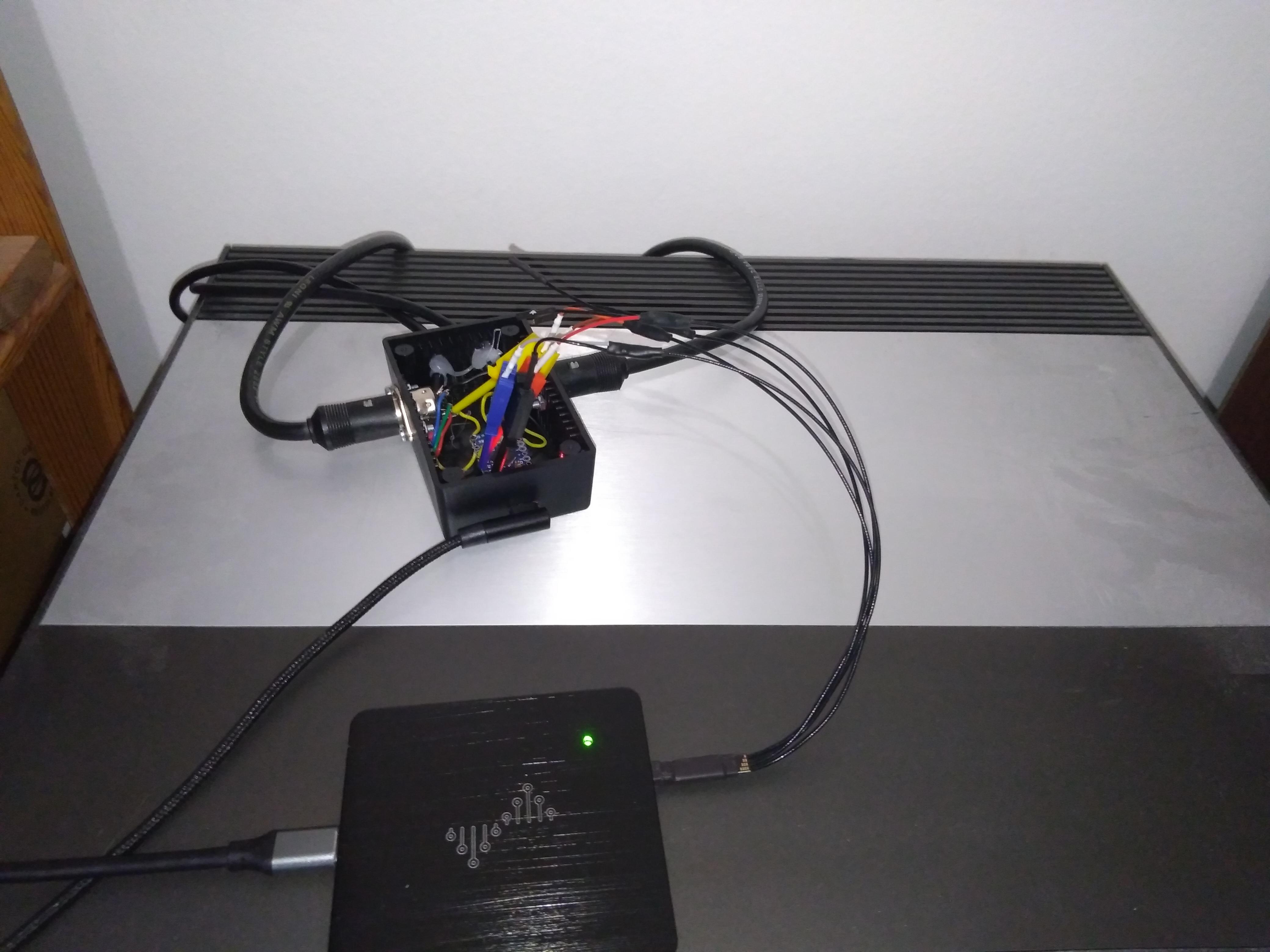
Sneak peek at my ongoing project !

Can confirm, currently hacking around with what I believe is the Datalink 86 protocol on my Beosystem 5500 ( so CD / TP / TP2 / PHONO ). TP and TP2 protocol are identical, except that TP2 has no support for running status (to provide the MCP5500 with live display).
CD and PHONO also seems identical, but I haven’t pushed the investigation enough to confirm that.
Stunning result you have here, congratulations !
I am very curious about that enclosure ! Is that something you designed ? Or is it an off the shelf part ?
Full disclosure here, I have an ongoing project that bears some resemblance with yours, but I have already settled on an more conventional enclosure.
Thank you for the links. I indeed had a look at them, but it turns out they are not comprehensive enough for my use case.
I will of course post my progress here, once I reach a point where I have enough to show to justify a dedicated thread.
Slowly reverse engineering the Datalink protocol used between the BeoMaster / BeoCord / BeoGram 5500, for a secret project.

That one is on me, it seems I was mistaken in my previous message : RL1 has NC contacts, so disabling the relay just kept the amplifier powered. The relay needs to be energized to turn off the supply to the amplifier.
This could normally be done by shorting the collector and emitter pins of TR19, but it uses the same 8V supply as the display LEDs, and since those don’t work, we can not rely on that supply still operating, so let’s not do that.
It’s been a while since I worked on mine, I don’t remember if P23 can be unplugged ? If so, unplugging it will prevent any power going to the amplifier (for real this time). The downside is it will also disable the 50/60Hz signal going to the CPU, and I don’t know if this signal is only used for time keeping, or for other purposes.
Once you’ve done that, you should check that the display is operating normally.
Not having the proper schematics certainly won’t help, that’s for sure, but I don’t think there is any irreplaceable parts in those models except for the ROM and maybe the transformer, so it’s most definitely fixable.
Seeing how the magic smoke escaped from the amplifier area, you might simply have a shorted output transistor (and the blown power resistor of course).
Hello,
I’m a month late, but if you are still looking for advice,looks like IC 1 ( display driver ) is having trouble. It is also in charge of producing the control signal for RL1, the relay that switches power to the amplifier. I’d bet thats the relay you hear clicking, and that’s the cause of the burnt traces (each times it closes there is inrush current charging the large C6 / C7 capacitors)
I’d start by removing R34. That will prevent RL1 from closing, hence cutting power to the amplifier. That should avoid any more damages in that area.
Then, look for issues around IC1
Hello Emma2,
I have contacted you by PM.Best regards
Hi Martyn,
I don’t have this issue with my MCP5500, but I’ve starred at its schematic for some times for another project.
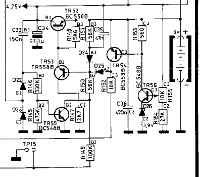
4.75V accross R149 seems quite high, as that would imply about 8V of battery voltage.
Can you check that resistance of R149 is indeed 100k ? ( that might require desoldering one of its legs ).

Hello,
I apologize for having neglected this thread for the last few weeks. Although I was very quiet here, things were still happening ( albeit a bit slowly ) to run a second batch of kits.
I have received this week all the parts for a new batch of PCB. I still need to program and test these PCB, but I should be able to resume shipments starting from the next week !
Pricing stays at 60€ + shipping.
Just like the previous batch, contact me in PM to order one.
Hi lumbergh,
Sorry for the delayed answer, I a bit behind on my mails !
Sadly I’ve sold the latest kit of the first batch, but I’m currently planning to run another batch ( components availability is a bit hit or miss right now, and prices have yet to come down ).
I’ll announce here when the next batch is ready, stay tuned !
Hello Yann,
I’m afraid I am not familiar enough with these circuits to offer any meaningful clue on this issue.
I can just wish you to find someone with experience on those.
Best regards
August 30, 2022 at 11:17 pm in reply to: Help needed from Martin or other CD drive specialists #8177Hello YannChris,
I’m a bit late to the party, but after a close inspection of your 1st photo, the bottom right resistor looks suspicious to me.
According to the documentation I have for the CDM 2 ( not for this exact board ), this could be R3108, a 4.7 ohm resistor responsible for filtering part of the +5V rail.
Can you get a closer look ?
Hello 69er,
I have assembled a couple more kits this weekend, those are available right now, still for 60€ / piece + shipping.
Please send me a PM with your address so we can arrange the payment and shipping.
Best regards
Hi Rudi,
Thank you for chiming in on this thread, and hats off for the original design ! I cannot imagine trying to fit that design is such a tight space 30 years ago !
I do understand that the original issue is a degradation of conduction with the ribbon, but as you stated, the complexity of obtaining a new ribbon and the operations required to bond it properly both to the PCB and to the LCD do not make this path viable.
Also the issue is compounded in many cases by the old ribbon cracking, and the LCD breaking free from the aluminum body due to its adhesive foam failing.
However, this does not seem to be the same issue on the Beo4 screen ( cf Guy’s previous message ), as no ribbon is involved on the Beo4, and replacing the zebra strip does not seem to fix the issue. Any idea what might be happening there ?
Best regards !
One full line of pixel missing suggests that indeed one electrical connection to the driver chip was lost, so ordinarily I would jump to the conclusion that the zebra strip is responsible for this, but Guy’s experience tells another story !
I am not aware of other common failure modes for this, although damage to the conductive track on the LCD could explain this behavior.
Now I’m getting really curious about this issue ! If you still have one (or more) damaged screen in your possession, and are willing to ship them to France, please PM me.
Hi Pilatomic, In my experience Beo4 screens do fail, but replacement is actually quite straightforward because connection to the PCB is via a little rubber ‘contact strip’ – a replacement strip is provided with the new screen.
Can you describe me how the screen fails ?
I think there is a good chance the screen are actually fine, just not making proper contact.The “contact strip” is called a zebra strip, it is commonly used for connecting LCD displays, but the drawback is you now have to keep it under mechanical pressure to ensure a proper electrical connection.
Failure to maintain the correct mechanical pressure is, as far as I know, the most common failure mode for those kind of displays.
Bonjour,
Si vous n’avez pas pu obtenir cette information ailleurs, je possède un meuble similaire, les tubes mesurent 15 mm de large par 25 mm.Thank you @YannChris for trusting me with your remote !
Sorry @david656 I didnt see your message earlier. I have yet to own any Beo4, is it subject to the same screen failures ?
- AuthorPosts
