
Madskp
Forum Replies Created
- AuthorPosts
-
Had some time look further into it today.
Try the amp without speakers to activate from 0 to 64 to check all these segments. Usually there will be a “8” problem… and a problem with the source led.
The 7 segment display can show 88 i both display units.
It can be the chip or the power supply itself.
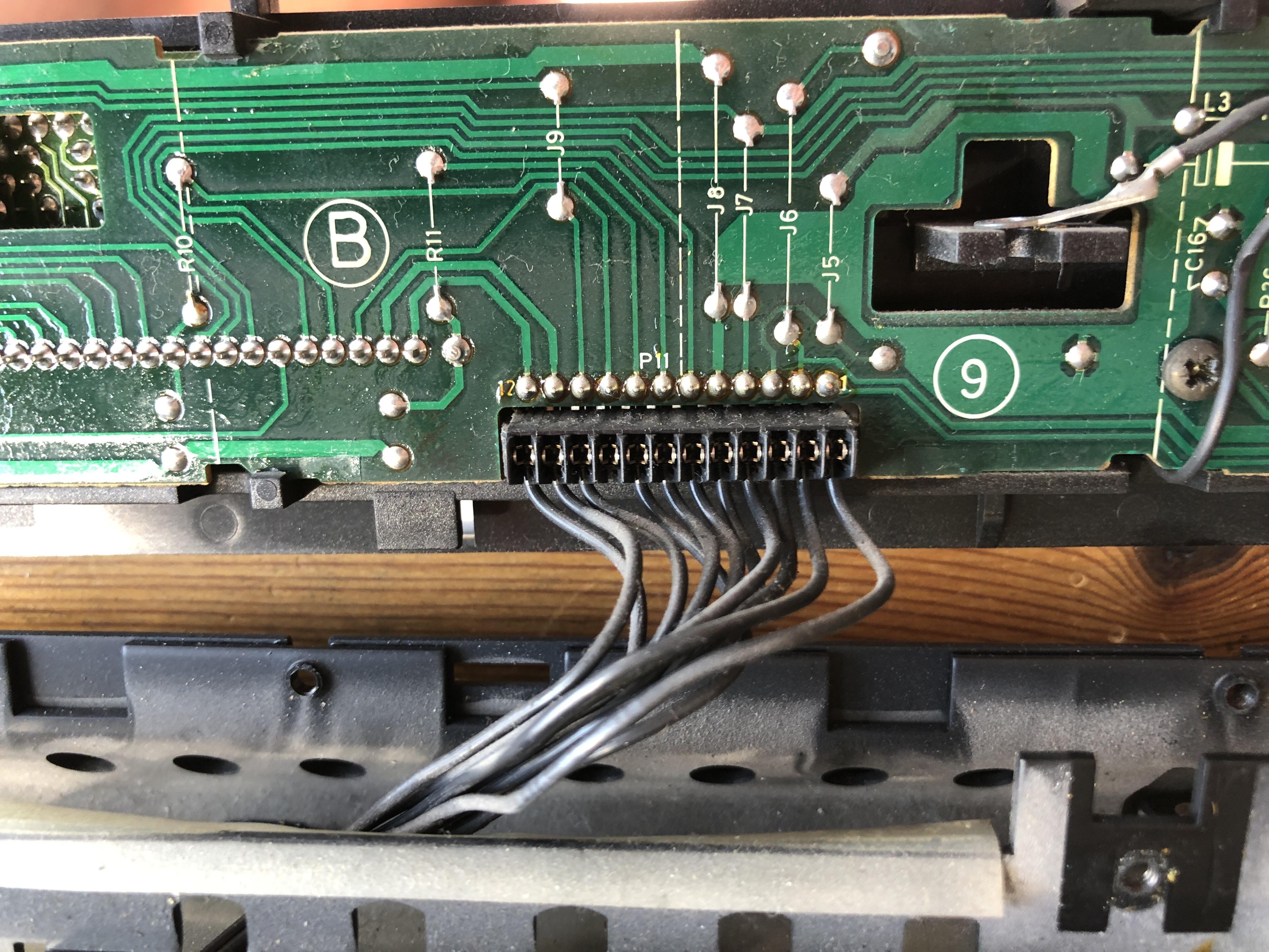
Power measured at pin 2 and 5 in connector p11 on the front panel PCB is 5,18V steady even with the flickering and relay clicking
About the relay clicking, now that I have the BM5500 open I can see that it is the relay behind the plug PCB that is clicking rapidly
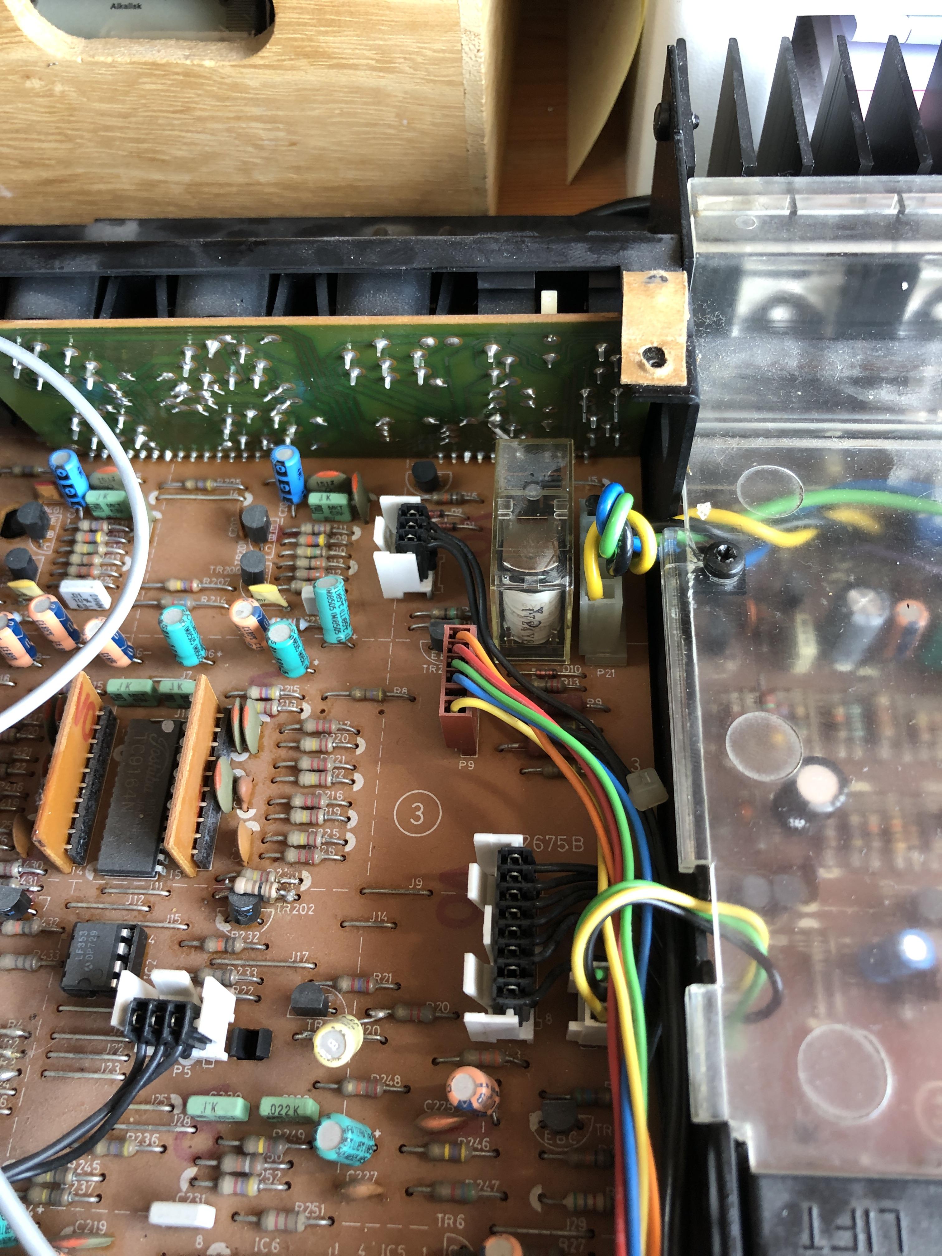
But I noticed that the relay on the PSU board (betwen the transformer and the large caps) is also clicking once in awhile if that is an indicator for something.
Usually some caps in the power supply are the cause…
Which caps would that be if I should try to test some of them?
Thanks in advance
Ok thank you, then I will take a look around there when I ger it open
Try the amp without speakers to activate from 0 to 64 to check all these segments. Usually there will be a “8” problem… and a problem with the source led.
Thanks for the input, I will try to look into that.
But just to clarify it is not the seven segment displays that flickers, but the names of the sources that are rapidly changing, each time followed by a relay click. Don’t know if that affects how you see the problem?
Measuring voltage levels on the 20 pin connector on the IR board all seems normal except for -5V which I can only measure at -4.3V, so here might be something
Tried measuring the -5V on the MKI and it shows -4.5V and that is working.
Another thing I noticed on the MKII is that the timer light is always on. If i touch the timer button and switch it to “timer off “the light will go out, but then turn on again when the text disaper in the display.
A few observations:
- I can not change option settings when the BL3500 MKII. is not connected to ML. This is possible on the MKI
- When I have it connected to ML (BLC1611) and change the option setting to L.OPT 4 also the service commands can not be done with normal commands.
- Measuring voltage levels on the 20 pin connector on the IR board all seems normal except for -5V which I can only measure at -4.3V, so here might be something
Oops didnt read your reply correctly. Will try with L.opt 4 later and report back
You are right that it behaves like it is in opt. 4 or 0 for that matter
however it is currently in opt 6, and then there is the errors related to ML
Just started a new repair thread to not drift to much away from the main subject in this thread. https://beoworld.dev.idslogic.net/forums/topic/beolab-3500-mkii-ml-error/#new-post
Apropos IR eye’s there is an LCS 7000 for sale on Ebay with a round IR eye only with timer and mute button. A little to expensive for my taste though
Will also test the BLC 1614 with the BL3500 MKI later.
Just did that, and as expected it does not work. The BLC 1614 is missing the supply voltage in the ML connection.
Might work with an ML powerbox, but these seems harder to find (at least here in Denmark) than a BLC1611.
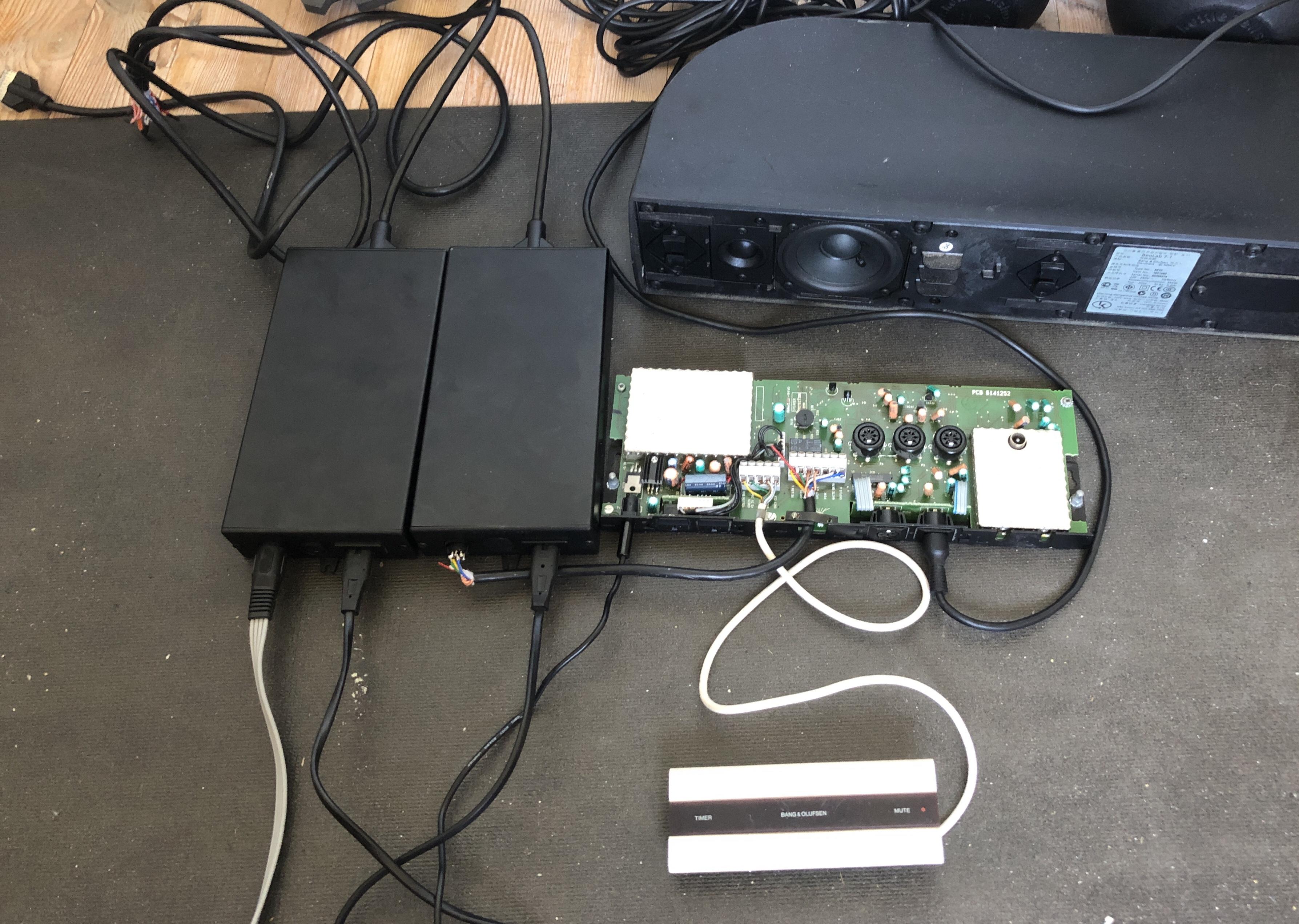
Was a little curious about the BLC 1610 so I had to open one up to see what is ticking inside:
All pins in use on the two ML connectors are wired in parallel, so just kind of an internal junction box.
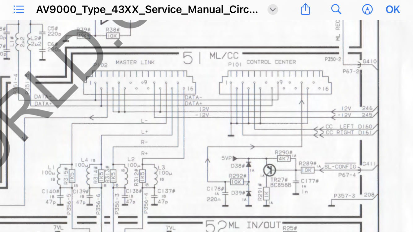
What is unusual with the ML connectors is that pin 3, 4, 5, 6 and 12 is all connected where pin 12 is supply voltage +, and most of the others are normally no used. This however explains where this box is getting power as the same pins are supplying +12V on the diagram for the AV9000
One other curiosity is that next to the external 1-2-3 switch is an internal switch with 2 positions:
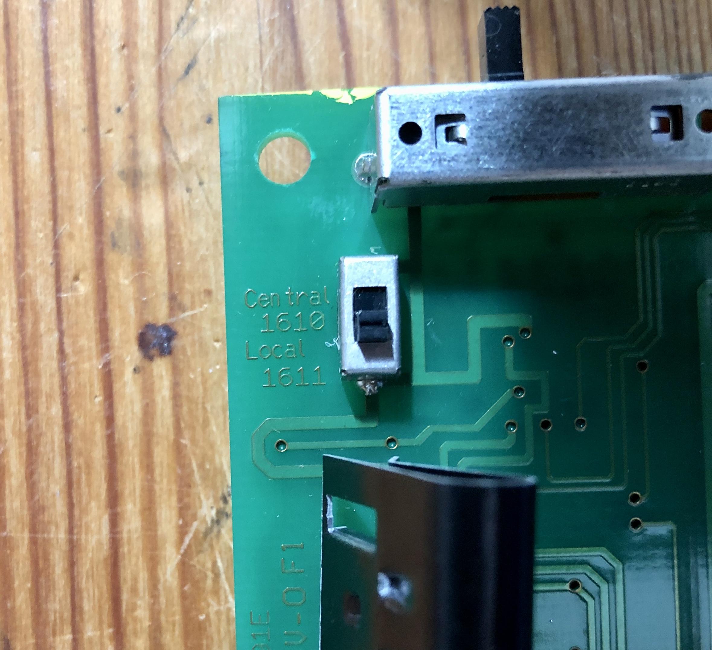
These are named:
- Central 1610
- Local 1611
Not really sure if that means it will function like a 1611 if it is in that position.
Might do some more testing around that at a later point.
Although expensive I can recommend the Almando Multiplay for this usage. I am using an earlier version of this product with my Beoplay V1 and a Sonos Connect as sources. Have been using this for almost 10 years now without any issues. One of the connected sources are playing straight through. When the other powerlink input is activated it switches to that instead.
As far as I know similar products called powerlink switch are offered by Bosscom and Oneremote.
I have no knowledge of how well they work.
And now for some BLC 1614 testing
Beocenter 6 (opt. 2) – ML – BLC 1614 – AAL – iphone.
Works with audio commands just as it did with the BLC 1611, so perfect for use for extra audio input on a ML TV.
For fun I also tried the BLC 1610 with the switch in different positions, but no response. One thing I hadn’t noticed before about the BLC1610 is the lack of power connection, and that might be why it only may work with an AV9000 system. Will open one up them up at one point at se whats inside
Beoport (opt. 6) – ML – BLC 1614 – AAL – iphone.
Working with video commands, bit not with audio commands for some reason, but can still give an extra local input to a Beoport setup.
Will also test the BLC 1614 with the BL3500 MKI later.
For good measure I also tried the IR board and the Microcomputer board from the MKII in the MKI , both at the same time, and in combination with the IR and Microcomputer board from that one, and that gives excactly the same result with the ML errors.
Pressing Menu, menu, 0, 2, GO now I sometimes get an error 1, 2 or 4 with both of my BLC 1611. hmmmm what to do
Started fault finding. Replaced the IR board with the one from the MK1 BL3500. Nothing changed.
Replaced the microcomputer board with the on from the BL3500, keeping the MKII IR board. Still errors.
Replaced both the microcomputer and the IR board. Now it works fine, so I think I can rule out the crossfield and plug board.
So the fault is probably in the Microcomputer or the IR board or both. Don’t know how dependent they are of working together from MKI and MKII.
Next step will be to control some voltages
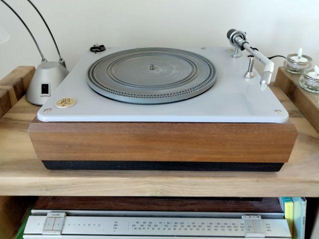
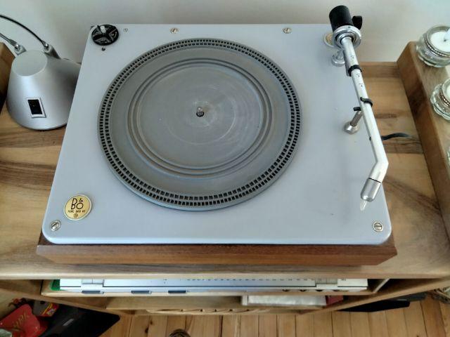
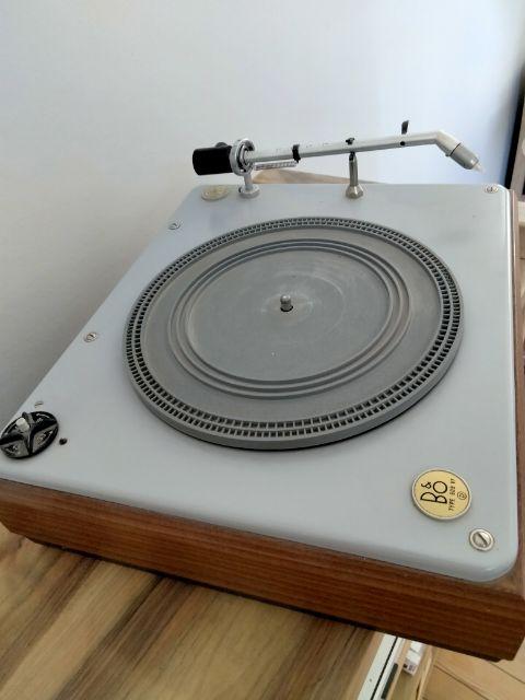
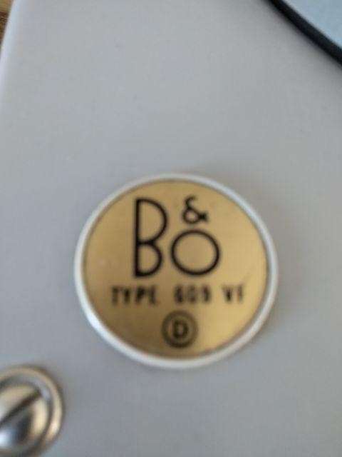
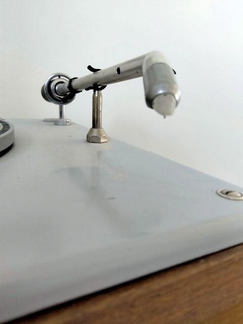
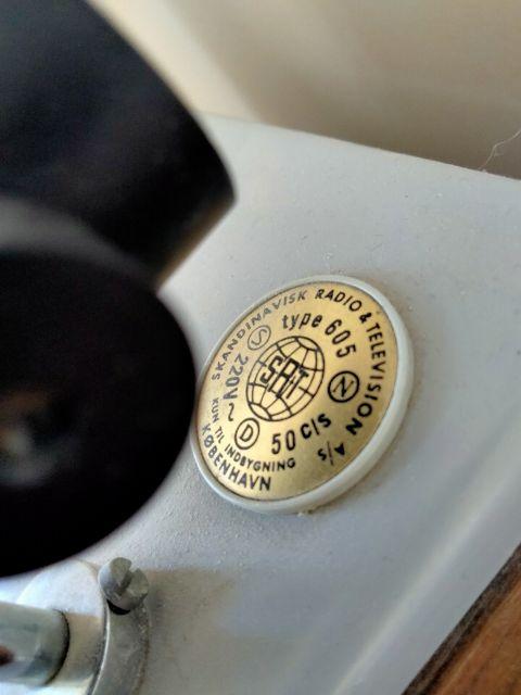
Here are some pictures of the Beogram
Now it’s going to be exciting to see if it will also work with the BLC 1615 as that combination could make a ML link room with local datalink inputs
Time to do some testing with some of the new equipment.
BLC1615 (SW 1.5) AAL connected to MCL screw terminal on MCL2AV:
BLC1615 pin 2 – > MCL2AV Brown GND R, Grey GND L, Shield GND
BLC1615 pin 1 – > MCl2AV Yellow L
BLC1615 pin 4 – > MCL2AV Green R
BLC 1615 pin 6 – > MCL2AV White Data
As audiomaster I used BLC1611. MCL2AV in option 1.5
I works. I get sound from ML through BLC1615 to the MCL2AV. It only reacts to audio commands. also tried to change to option 2.5 with no change.
Edit 2023.06.05 Tried the same test with BLC 1615 Sw 1.0 and 1.1, and this also works
Also tried it with a BLC1614 (SW 1.0) while I had it all lined up, and it worked the same as the 1615.
Ok so I did some testing.
The Beolink Passive does not use the “normal” speaker on/off signal on PIN 4 in the 8 Pin DIN connectors, but instead Pin 1 Power up.
I have a fully wired RJ45 to 8 Pin DIN female adapter that I made myself. It is wired as shown on page 104 in the Beolink handbook 1.9:
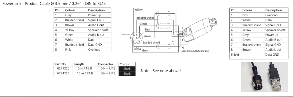
I tried connecting between my adapter and the BL passive with some different powerlink cables without succes. Then I tried with an 7 Pin audio Aux cable and that did work.
Testing with a multimeter I can see that none of my powerlink cable has connections on Pin 1, but the Audio AUX has that.
So in conclusion a cable wire like the one shown in the picture above should work.
Newer B&O TVs with RJ45 outputs don’t work correctly with Beolink Passive, as they don’t provide the correct trigger signals for the two trigger inputs of the Passive (one of these signals is missing in newer products).
I actually had a setup with a V1 and MCL2P at one point where I had the triggering working. I still have the V1 and also have af BL Passive, so I will try to make at test to see if I can get the V1 to trigger the BL passive, and report back about the cables and adapters used.
could be so useful for something …
I once heard that 1, is Masterlink mode, 2 is Nespresso mode and 3 is Dyson mode, but I’m not really sure, the guy and me were really drunk at the time.
I think 2 and 3 requires even more black boxes ?
- AuthorPosts