
Madskp
Forum Replies Created
- AuthorPosts
-
Guy is correct in this.
C will also work in combination with a Male-Male scart cable if you need more lenght.
In the setup menu for the AV input Beocenter 2 can be choosen the same way a PUC code is selected. Only difference is here you dont need an IR blaster as the controls happens via the scart adapter
Keiths post in this old thread https://archivedforum.beoworld.co.uk/forums/t/42470.aspx says that the Powerlink functionality of the BL3500 in combination with the wireless 1 is from SW 3.33, so the software version of the BL3500 might indeed have something to say in how it reacts to the PL connector input.
In this newer thread https://archivedforum.beoworld.co.uk/forums/t/36474.aspx however version 3.1 is said to provide wireless comptability, so migth not make difference up to 3.33 in that regard.
I have to find a set of wireless 1 to test this further
One of them is an external black box for the MKII BL3500
There is a post ( https://archivedforum.beoworld.co.uk/forums/p/31274/251443.aspx#251443 ) in one of the older forums that mentions that the box has a Masterlink and a powerlink connector, so sounds like it could be something like the Almando Masterplay.
I am beginning to wonder if that PL connector on the MKII ever was supposed to work other than with the Menu, menu, 0, 4, GO command, or if there is different behavior with newer software versions
Keiths post in this old thread https://archivedforum.beoworld.co.uk/forums/t/42470.aspx says that the Powerlink functionality of the BL3500 in combination with the wireless 1 is from SW 3.33, so the software version of the BL3500 might indeed have something to say in how it reacts to the PL connector input.
If it is data from Powerlink pin 6 it is reacting to there might also be specific data from the wireless 1 that will make the Bl3500 react, so it migth not work with other power link inputs.
In the same thread a modification to the BL 3500 from Iconic AV is also mentioned, that should make it work like any powerlink speaker. That sounds more interesting. Of course there is no word on how comprehensive that modification is.
Did some random google searching about BL3500 and Powerlink. In a thread in one of the older forums there was a dead link to a modification from a french company. However the main site is still active and has some modifications http://www.bang-olufsen-sav.com/Kits-lb3500-bbeaaaaaa.asp
One of them is an external black box for the MKII BL3500, the other seems like an internal modification for the MKI BL3500.
Not much information about how it is working though, and the price is much higher than a used BLC 1611, so might not be that interesting.
Great result finding and fixing the ML fault
Yes that was nice that is was fixable.
Only downside is that now I have a faulty where I introduced a missing component making it even harder to diagnose 😉
As noted in the repair thread https://beoworld.dev.idslogic.net/forums/topic/beolab-3500-mkii-ml-error/#post-21410 I now got the ML functions working again on the MKII BL3500. It was a fault on the IR board that messed up the ML signals.
Trying to replicate the previous test with all the MKII components in the BL3500 again..
ML disabled on the BL3500 and in option 0 (also tried option 4)
BL Active in option 6 as Powerlink output, and BLC1611 as Audiomaster with and Iphone for sound.
Activating an audio source (A.TAPE) on the BL Active nothing happens on the BL3500 as for MKI.
A press on the Mute button on the BL3500 does nothing.
In fact the mute button doesn’t seem to react at all if ML is not activated and connected to an ML master. This also applies to the ability to make option setting.
With Bl3500 in option 4 it won’t respond to the Link IR commands. Also here I think it will only do it with ML active and connected.
So actually this result is worse than with the MKI hardware in place.
I am beginning to wonder if that PL connector on the MKII ever was supposed to work other than with the Menu, menu, 0, 4, GO command, or if there is different behavior with newer software versions
Now I will try to source these components and see if replacing them makes a difference.
I found a replacement for TR14 in a faulty BLC 1615. Its an SMD part named BSS84. The marking on the part can aperently differ. The faulty one had the marking YBs, where as the other part and also the one in the MKI was marked SPs.
I found a matching diode to replace D8 on some scrap electronics. A little larger part but it could be mounted in an angled position.
The result is not pretty, but now ML is working again with no errors, and it responds to source commands when connected to a ML master.
 So now it’s back to the other thread for testing again.
The service manaul for the MKII states that in case of an error 4 on should check the cables and the signal path (amplifiers in the data transceiver circuit).
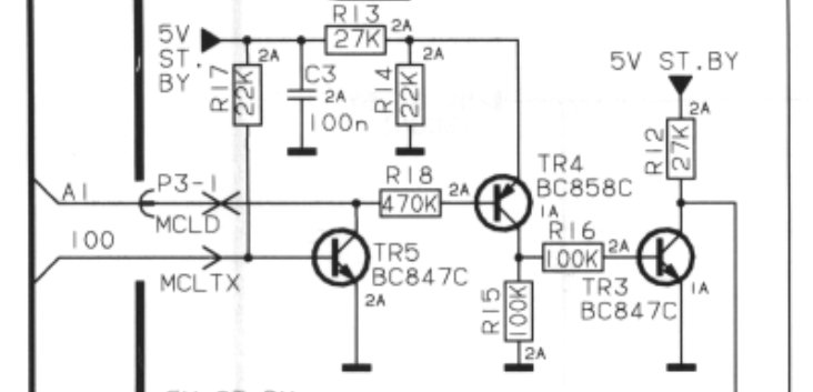
As the MKII service manual don’t have diagrams I am using those from the MKI servicemanual.
In that there is shown a transmitter and a reciever circiut for ML on the IR board. The transmitter part has some transistors where the reciever par has some IC’s. So I choose to focus on the transmitter part.
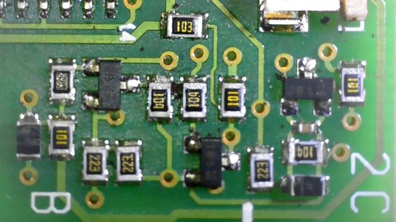
I tested all transistors and diodes and found that TR14 is not recognized by my component tester (so might be faulty) and D8 is short circiut.
Here is a picture of the placement (D8 is removed when I took the picture)
The placement of D8 is not the same as shown on the PCB layouts in the MKI service manual.
Now I will try to source these components and see if replacing them makes a difference.
Any insights as tho why the might have gone faulty are very welcome if I am overlooking something.
Then cleaned up yet another Beo4 remote and must have been on auto-pilot because I didn’t spot the obvious mistake until re-assembled!
that is perfect as a IR command converter then ?
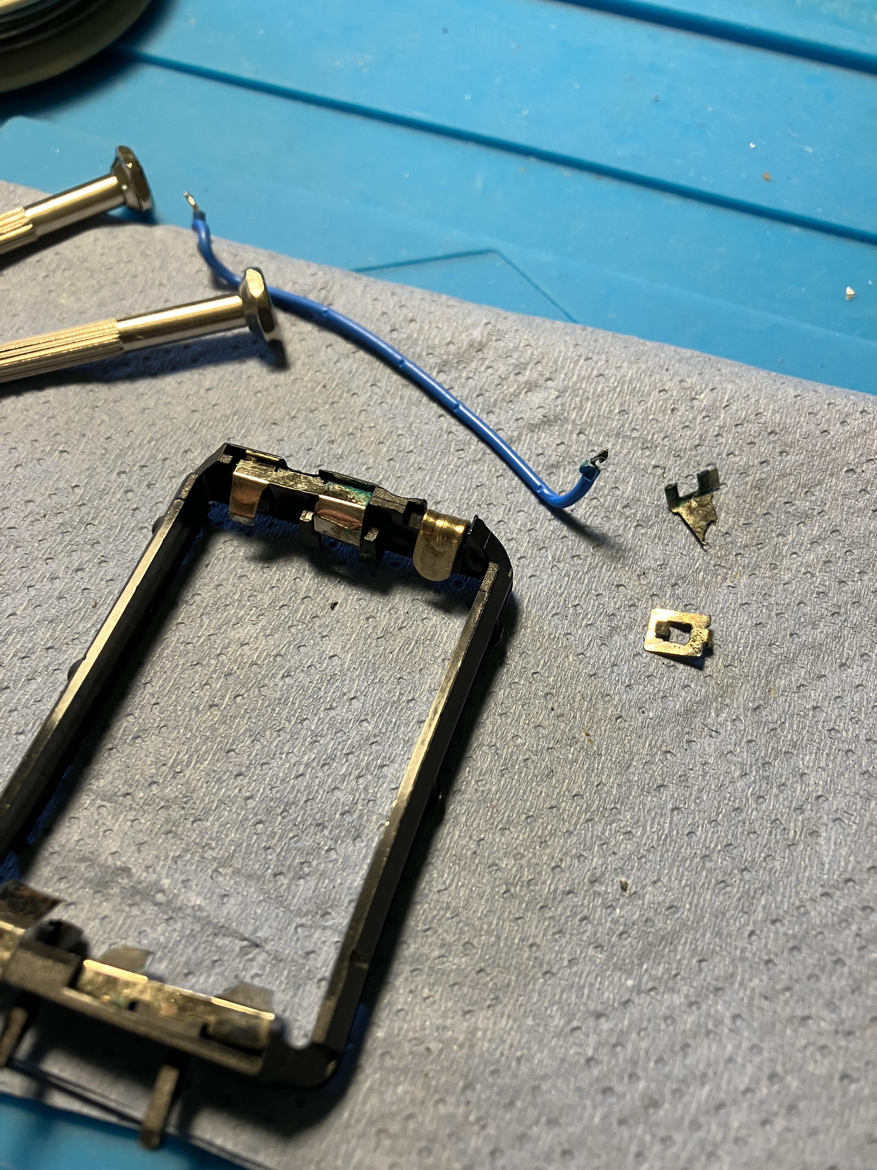
Battery acid corrosion had broken the negative terminal in my Video Terminal’s battery compartment, so I made a new terminal using a re-purposed picture hook.
great job of re purposing other materials for these repairs. At some point there might not be enough donor remotes for spare parts anymore.
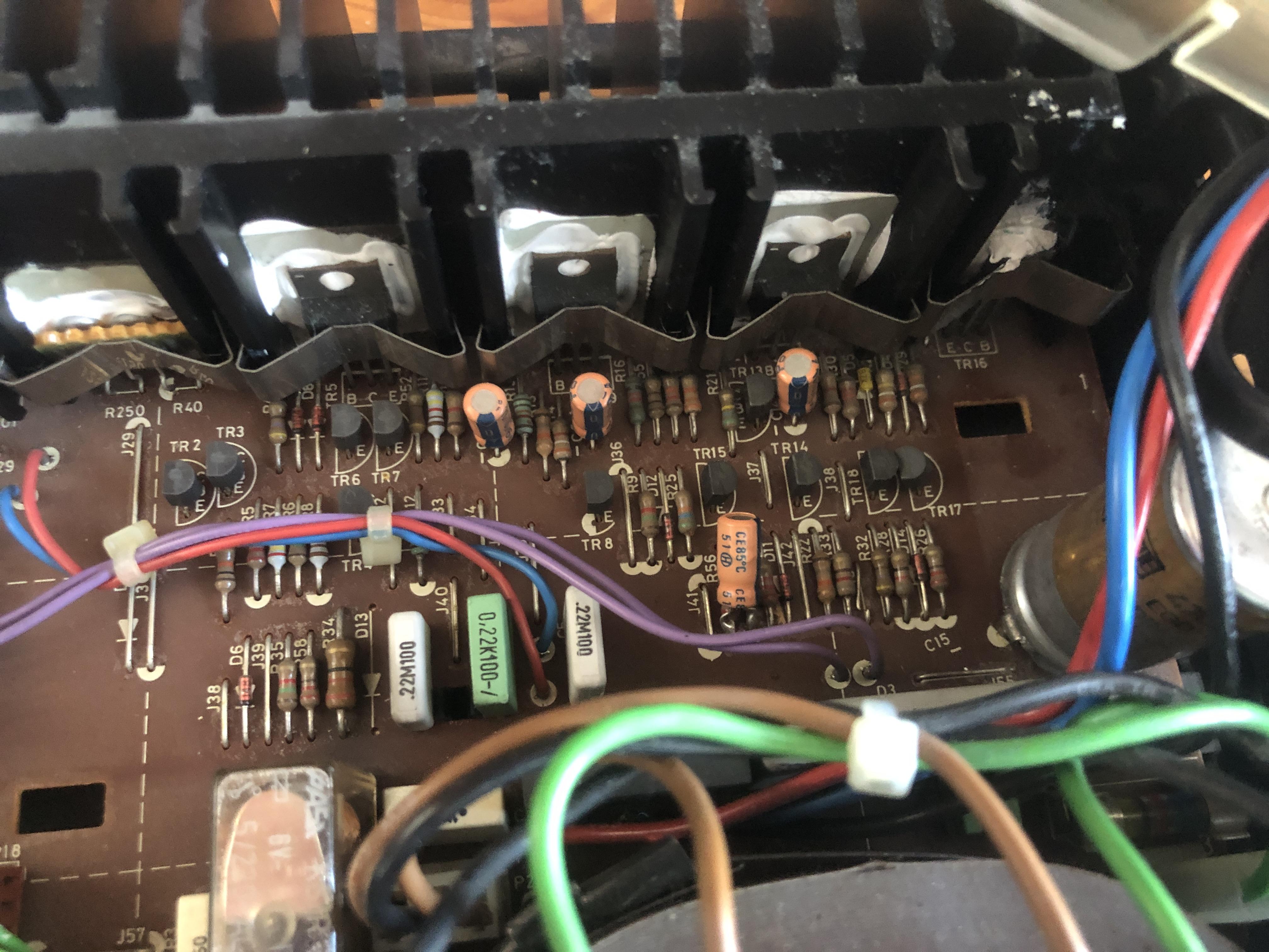
Usually some caps in the power supply are the cause…
Is it those orange 10 uf caps here, C8, C9, C14?
At the handbook they refere to pin 7 with the “braided shield”, on my cable it’s the other way around. Pin 2 has the shield and 7 the other ground. I can try to change it around, but since it’s working with this cable on my Beosytem 3, i don’t think it’ll work. But it’s easy to try!
that might have something to say.
With original powerlink cables this behaviour can also differ from product to product depending on the type of powerlink cable used
I just desoldered pin 7, which i connected to pin 2. And the deeper hum was back. When i touched the (loose) wire 7, to pin 2, the hum was gone again, and only the high pitched “static” was back.
I am a little unsure what you actually did when you write that you desoldered pin 7 and connected it to pin 2, but you also have a loose wire?
Just to clarify my idea was to remove the connection to pin 7 in both ends of the cable and not use that wire at all as the wire on pin 2 also is a ground connection.
Not sure if it will work as the official B&O powerlink cables does have both ground connections.
Also maybe check your pinout with those in the Beolink Handbook from page 102 https://beoworld.dev.idslogic.net/beolink-handbook-version-1-9/
Note that there are several versions.
If I remember correctly there was a post in one of the archived forums (can’t find it right now) that mentioned that if a timer was set with a MCP 5500 it can not later be deleted with a MCP 6500 or Beolink 7000. I think that was the only “limitation” mentioned in that thread.
I will post back if I find it againSince I can’t count on the IR board and Microcomputer in the MKII BL3500 to test the PL functionality I decided to install those from the MKI in the MKII.
ML disabled on the BL3500 and in option 0
BL Active in option 6 as Powerlink output, and BLC1611 as Audiomaster with and Iphone for sound.
Activating an audio source (A.TAPE) on the BL Active nothing happens on the BL3500. But a press on the Mute button on the BL3500 will make it start on A.TAPE and play the music. Volume control is somehow possible, but the BL3500 seems to compensate and lower the volume changes from the BL active.
Standby command from the BL Active will also shut down the BL3500.
The interesting thing to know here would be if this behaviour is different with another SW version in the BL3500 microcomputer, and/or if it is different if a BL Wireless is used instead of the BL Active
Hello
At least in some products pin 2 and 7 are internally connected in the device or pin 7 is not connected at all.
An idea could be to disconnect pin 7 in the cable to see if the hiss disappear. My suspension is a ground loop.
A little test to see what is happening when powerlink is connected to the MKII BL3500. Powerlink signal from MCL2AV.
When in standby the voltage at MCLTX is 4.93V, and when powerlink pin 4 SP ON is activated MCLTX drops to 0V. That could be an interesting lead as to how the speaker should be activated when in working condition.
On MCLRX I see small voltage drops when a remote command is used, much like when measuring on MCL data lines, so nothing I can make anything out of.
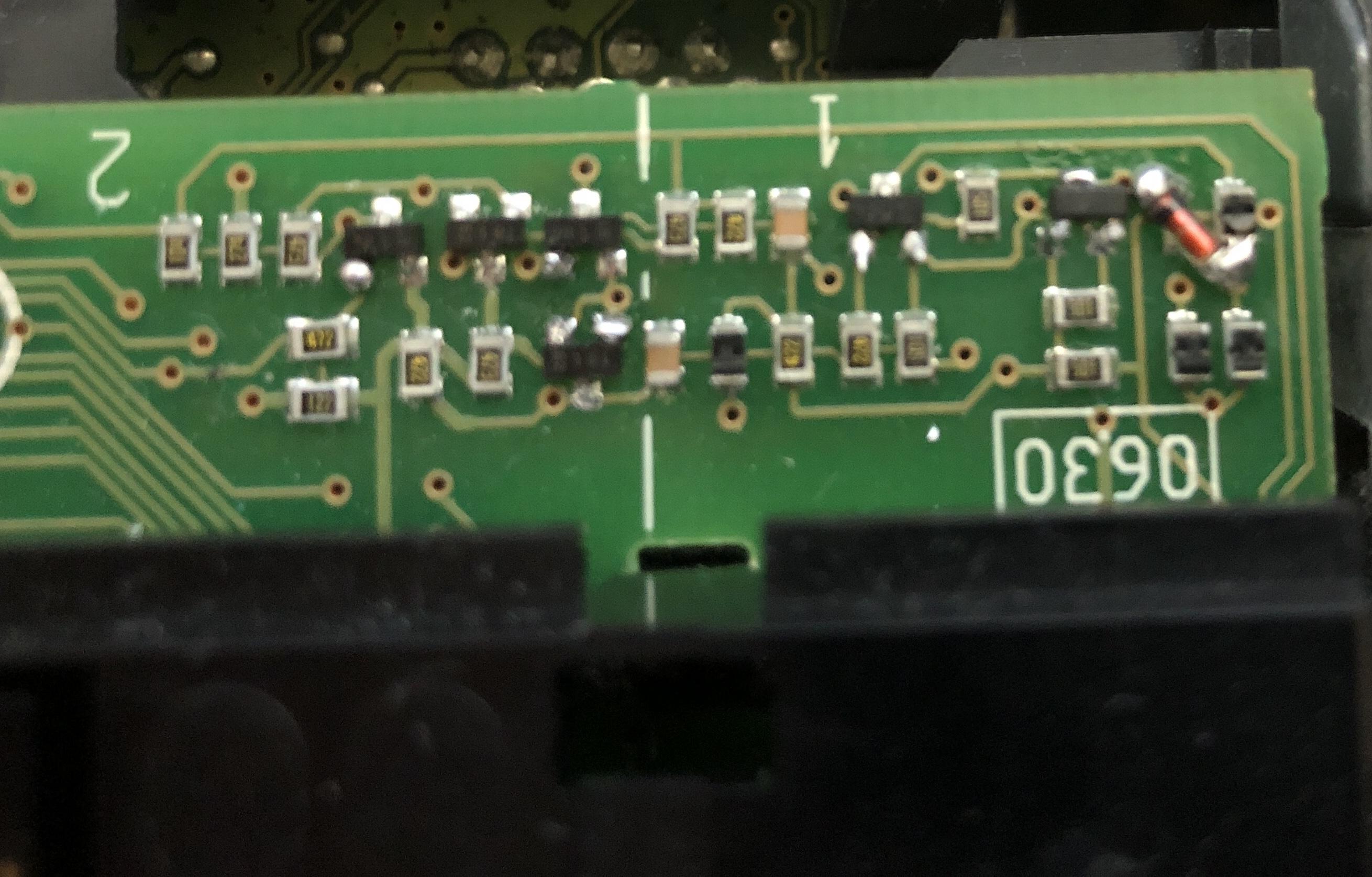
It took some time, but I now think I have found out how the circiut is constructed in the MKII. I used both multimeter and microscope to spot all the connections. Microscope picture here:
And from the the other side of the PCB:
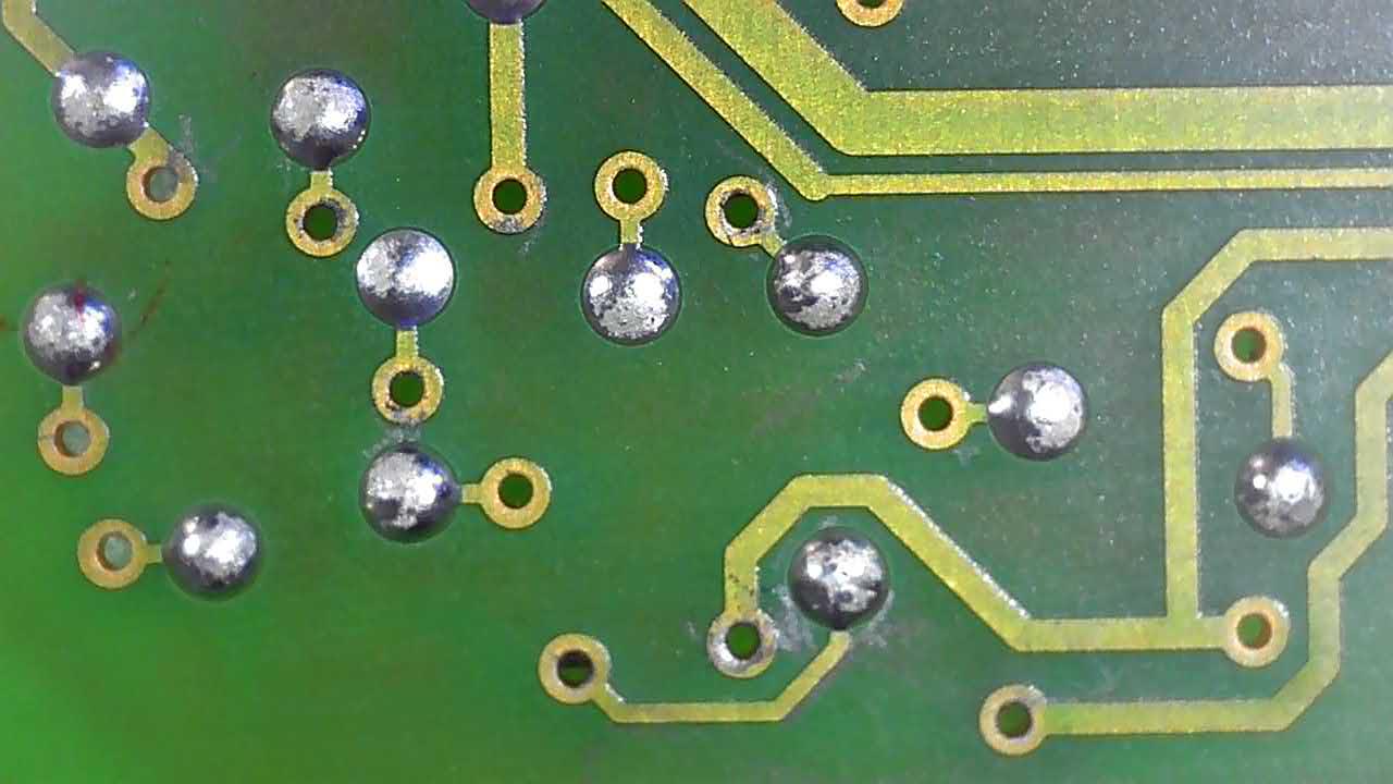
Most of the VIA’s just end up in testpoints with a solder blob on them. This is a little confusing when trying to figure out where the traces go.
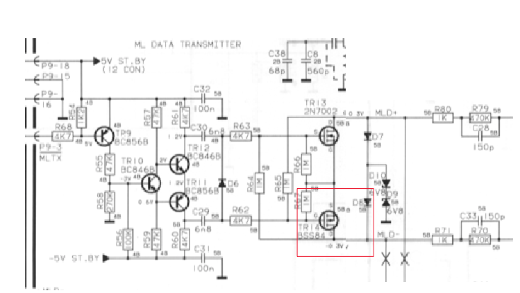
This is how I have analysed it to look like in diagram form. I have tried to make it in the same form as the diagram in the MKI service manual to make comparison easier.
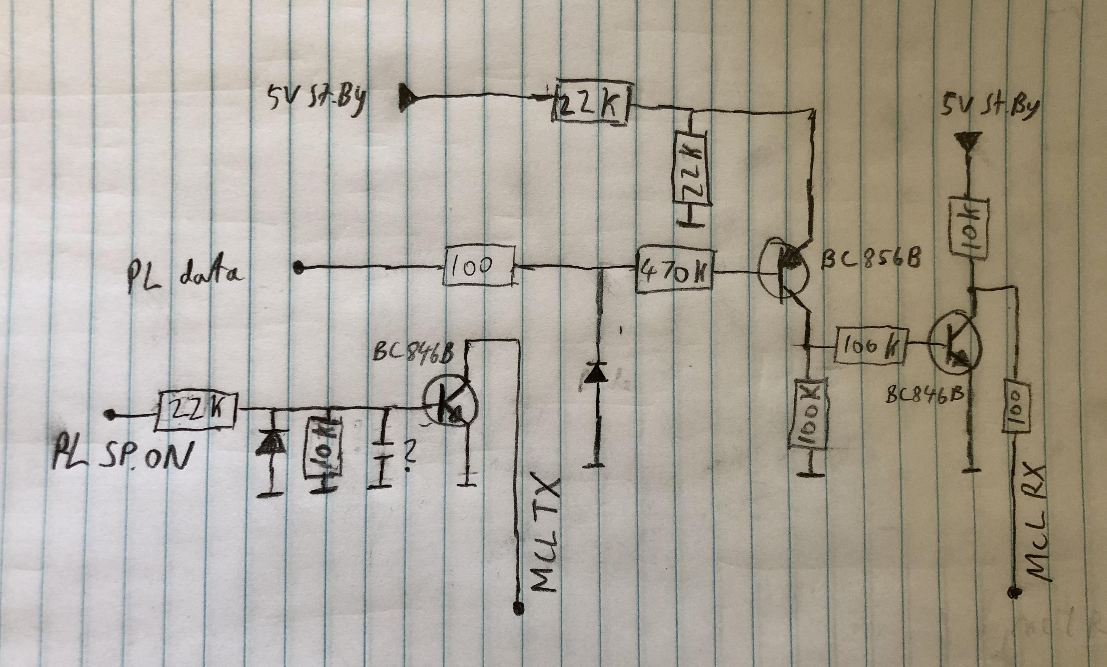
I have used the names from the connectors in the MKII servicemanual. It might be a little confusing as there is both use of PL and MCL in that.
One thing to notice is that the circitry is now divided in two. One with the PL sp.on from PL pin 4 which is connected to MCLTX, and one with the PL data from PL pin 6 which is connected to MCLRX.
Event though the BL3500 MKII is faulty I can still do some detective work on the PCB’s about the PL connection.
Pin 4 – Not really sure. I measure 100 Ohms resistance between the numbered soldering point and the pin 3 on the flat cable to the crossfield PCB. It is called SP ON on the block diagrams in the servicemanual. Unfortnuatly I can’t trace it further from the connecter on the crossfiled PCB which looks very much the same as in a MK1 BL3500
I have to admit that I was wrong in my quick assumption that the Crossfield PCB’s was that same in the MKI and the MKII
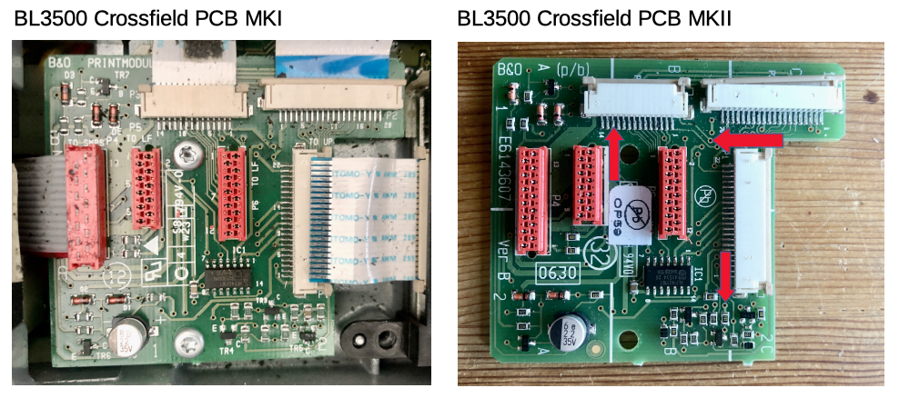
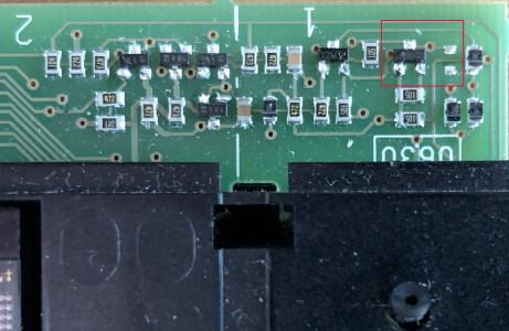
Having a harder look and probing with my multimeter I found the place where the connection from PIN 4 on the powerlink connecter goes. I have marked the route with red arrows on the above pictures. It ends up in a area with 3 transistors and some other components in the right bottom corner. The PL data signal is also comming to this area.
This area is clearly rearranged compared to the MKI.
Looking at the diagrams for the MKI I can see that this is where the MCL data signal come in on that and pass to the microcomputer
I have yet to analyze how the PL pin 4 signal is comming in to this circitry, and if there are changes in it.
One thing is for sure though. The PL pin 4 signal is not present in the MKI.
I have done a test with the MKI earlier https://beoworld.dev.idslogic.net/forums/topic/bl3500-and-the-mcl-pl-connector/page/2/#post-17635 where I was able to activate the speaker with powerlink data conncted instead of MCL data, so the use of the PL Pin 4 signal might have to be in combination with powerlink data.
I just did a quick test on the MKII with powerlink from my MCL2AV just to see if it would activate anything, but no luck. However that could be due to the other faults I have on it.
Just being a little curious I downloaded the image and are looking at the windows installation at the Norton Ghost image.
But I haven’t stumbed upon a BS5 program folder or file. Isn’t there one, or is it just burried deep down in the folder structure?
- AuthorPosts