KolfMAKER
Forum Replies Created
- AuthorPosts
-
Hi @Beo3000fan
Thanks for the extra pictures.Can you do following?
- Make a picture of the backside-panel (the one you took away to see the inside)
- Let me know the measurements of the loudspeaker box (W x D xH)
Thanks for sharing your idea Olivier!
The Grundig box 45 comes close, but is not the same. The speaker we are looking for has horizontal slits, instead of vertical.
Also, the front panel is completely integrated with the speaker casing. It does not look like it can be taken off to access the drivers. This looks different on the Grundig 45.
That’s why I think it is interesting to see the backside.
(Maybe, it is not a loudspeaker;-)
- Can you share more pictures?
- Also one from the backside?
- Are there any labels visible?
It looks a lot like one of the speakers in the Grundig line of ‘Grundig HiFi box Lautsprecher’. For instance the Grundig HiFi box 740:
https://www.radiomuseum.org/r/grundig_hifi_lautsprecher_box_740.html
But it probably is a different model. What I can say is that Grundig produced several speakers, with all wood front grilles. And with the slits horizontally. The 740 and 525 are examples of this design.
have a look over here:
http://www.hifi-wiki.de/index.php/grundig_box_525
This Wiki has an over of most grundig loudspeakers with specs and pictures.
By the way, most Grundig all wood loudspeakers with horizontal slits, were produced in 1970.
Ah, I did not understand that you had the 5 volt connected most of the time.
I expected that you were mainly talking about the RCA connection between Sonos and BeoLab.
Another suggestion for you, to make things easy.
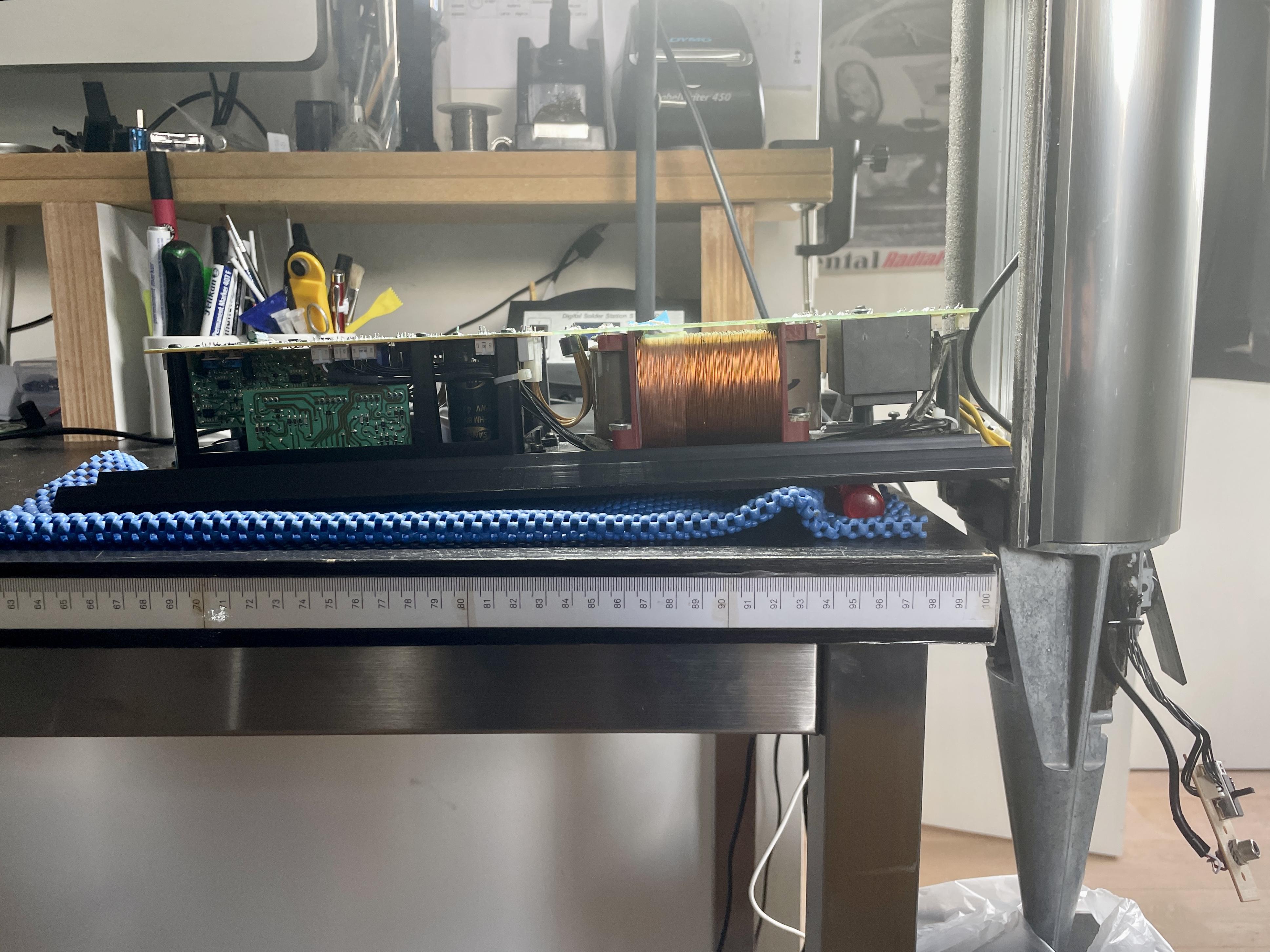
If you keep the BeoLab 8000 in an upright position, then you can more or less ‘unfold’ the lower panel with the PSU and the Amp. So to speak; ‘turn it as a hinge’. (See picture)

If you work this way, the power- and the two JST-connectors will still be connected (via the bottom of the speaker casing). So the PCB’s will be powered as normal.
But also, you will have easy access to the trace-side of the PCB to do your measurements. Because it will be face up to you.
Mark II has serial number 1699 2475 and up, and B&O started producing them in 2002.
Production in year 1999 is serial number 13xx xxxx and up.Back yo your issue …
- So the issue is with one speaker, check.
- Yes, check if there is a temperature difference. I would assume there is one, and it should of course be with the faulty speaker.
- Good to know you checked the foam inside. If you see white foam, it might be ok. It might also be that an owner before you already made that change, but that damage by the old foam already happened.
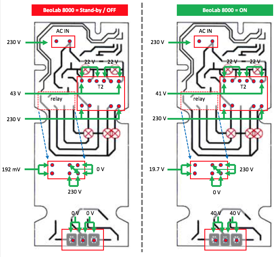
I recently also had a problem with a BeoLab 8000. Not the same as yours, but it made the speaker behave uncontrollable. By measuring the voltages on the PSU board, both in stand-by/Off an On, you can at least quickly check if they are right. In my case I found out that the T2 transformer was about to break, which it in fact also did a few days later.
So here is an overview of the PSU/PCB 01, and the voltages you should measure (in stand-by/Off and in On mode):

If all voltages are good, the issue is not the PSU section. Then you have to look into the Amplifier section.
Hi carljh,
Interesting story you have here.
One thing upfront, BeoLab 8000 MK2 has serial number 16992475 and up. So if you have serial 15xx xxxx, it still is a MK1. Not bad, also a great speaker!
Your remark at the end makes a lot of sense. This looks a lot like overheated components that make the protection circuit switch off. Especially, since you also describe that if turned off, and you pull the plug from mains and replug it, it only stays on for a while. Seems a lot like a overheating issue. So here’s some suggestions:
- I assume you have a set of two speakers. If so, do you have the issue with both speakers or just one?
- If it is one, touch the cool ribbon part of the PSU/Amp panel (the lower part of the front panel). Do that for both speakers. Do you feel a temperature difference?
- What you can do is unscrew the PSU/Amp panel (6 torx screws) and pull it out. Be aware that on both sides there are cables and connectors that need to be unplugged before removing the PSU/AMP panel, with care! When pulling out, check if you see foam that has been disintegrating. If that is the case, you will probably find it sticking to the PCB and components. This can easily cause overheating and malfunction. (I know that from a certain serial number onwards, the foam that disintegrates has been replaced by B&O for a newer type. The old type can be recognised by the dark brown color. The newer foam type can be recognised by the white color.
Hope this helps.
I can recommend ’beolover’. To my knowledge, he is the expert on repairs and restorations of the BeoGram 400x.
You can find his name on the forum and send him a PM. Or check over here.
OK, clear.
About the BeoSol product; I have tried to get into contact with him. But I haven’t got any reply.I have done extensive searching on the internet, but haven’t found that same box, or an alternative that also works autonomous.
I do like his product, because it can sense an audio signal and then automatically send the trigger signal to the right Powerlink pin. Like you say, this is an autonomous working product.
I will keep on searching, and I am also looking into building a circuit that handles auto audio signal sensing and auto sending a trigger signal. If I have any news, I will report back.
Hi RP-BEO7-32,
Which BeoLab speaker do you need it for?
Best,
KolfMAKER
Hi Filipbrugge,
Do you have a deep scratch?
I have experimented with a chrome type of repair marker. It worked quite well to cover the deep scratch damages.
Hi Matador,
A wall stand for €69,- sounds like a good deal. The tabel stands that I have seen are around €150,- (pay attention to shipping and import costs).
Other alternatives besides a 2nd-hand original are either a self-built stand, or a 3D printed stand similar to the original.
A 3D printed stand in metal will easily over exceed €150,-. But if you would print one in ABS or PLA and you know someone with a 3D printer, it could be affordable. ABS can after printing be finished with a metal look.
Anyhow, of course you also need a 3D model of the tabel stand. It could be that someone had designed it before, or you need someone to design it.
By the way, I have a 3D printer and I also design 3D models. I could create the BeoLab 3500 table stand if I had a physical example.
Is this the table stand you are looking for?
What is the price when you buy one?

Let’s see if we can interest people reading this thread, to offer repair to you. So let’s get some description about what is wrong.
Can you describe a little bit more what is wrong?
In which country & city are you located?
Thanks for reminding Beobuddy.
I have just sent a PM for ordering a T2.@ beoladdy
Yeah, I have seen the Kosetrading part. Unfortunately it’s the whole PSU-PCB, not only T2. And also it’s a lot of money to solve a dead T2 trafo.
Sure, I will let you know about the RS Pro trafo.
January 3, 2023 at 1:04 pm in reply to: BeoLab 8000: 5-pin cable from RCA-PCB to LED-PCB sensitive #13565@ Luke & all
Thanks for hopping into the other thread (this one)
If I now look back to my issues described in this thread, I start thinking that a lot has probably been caused by a dying T2 Trafo. As described earlier in this thread, I already noticed an inconsistent voltage on the T2 output side:
- 20 volt on pin 7 & 9
- 23 volt on pin 10 & 12
And a few days later it now looks like this:
- 0 volt on pin 7 & 9
- 0 volt on pin 10 & 12
So I suspect that T2 is or is big part of my issues. I will now first place a new T2 trafo, measure and test again. And then come back to the forum with an update.
@ beoladdy
Very interesting. I have a BeoLab 8000 that started having problems with switching ON>OFF>ON continuously. See this thread.
After measuring all over the PSU PCB I found inconsistent voltage on T2: 20 volt on pin 7 & 9, and 23 volt on pin 10 & 12.
Just a few days later, the BeoLab was completely dead, like you describe. Measuring T2 again shows: 230 volt on pin 1 & 6, and 0 volt on pin 7 & 9 and pin 10 & 12. So the same situation as yours.
@ Luke466
Thanks very much for sharing your experience with the RS Pro replacement trafo!
So thank you both, I consider my problem with the dead BeoLab 8000 solved.
Though I will post again when I have replaced T2. - AuthorPosts
