Glitch
Forum Replies Created
- AuthorPosts
-
et me know what you guys think.
From a general sound perspective, I don’t see any reason why it wouldn’t work. As long as you keep the cabinet volume and reflex tube length/diameter the same you will, in general, have a similar frequency response. Even if you mess up the very low frequency response, this won’t be critical for voices since they don’t contain those frequencies.
Would you actually be happy with the form factor? I’m having a hard time imagining what this would look like under a TV.
Did you plan to have the bottom-most mid-range close to the floor? Not having the tweeter and mids at ear level may mess with the vertical dispersion. I don’t know if this is a better or worse trade-off versus having the mid-range array horizontal.
Have you considered using a (well matched) pair of Pentas (in the original configuration) placed tight to sides of the TV? The mono pair would provide the a solid centered image and the apparent sweet spot could be roughly controlled by the angle. The other “surround” speakers could also be Pentas for the full overkill effect. 😉
Glitch
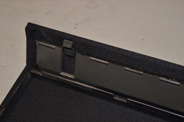
It has been long enough where I’ve forgotten most of the finer details of recovering these grills. Hopefully you can see what you need from the picture.
Taking the grill off reminded me of how precarious the procedure feels. No matter how many times I’ve done it, it always seems like something is about to break. 😉
Glitch
I used iCraft Supertape based on several recommendations in another forum. It has been seven years since I changed the grill cloth and it is still holding strong.
Glitch
It is good to hear that you have made progress.
One tip related to changing the grill cloth is to use two sided tape to attach the new material. This makes it much easier to get the tension just right versus using glue.
There are a many other tips that people can provide for Pentas. You probably have already figured out that B&O enthusiasts are pretty passionate when it comes to Pentas ;-).
Glitch
Meantime I sliced the front off this cartridge where the cantilever had broken off.
Pictures please. I, and likely many others, find it very interesting to see the inner workings of things that people normally don’t cut apart.
It also might be worth a search of the forum history to see if anyone has tried this before. One of the more recent similar threads is here.
Glitch
These decks can be made functional (although longevity is not a guarantee) with a parts machine as a donor
This has never worked for me… Eventually, I always fix the donor machine and it becomes a spare/backup machine ;-).
It would be nice to find a OK lower end cartridge with intact needle for this at a cheap price out of dead broken machine.
This is possible, but you will need to be very, very patient while waiting for something to become available. I think that many of the old B&O turntables get taken out of service when something happens to the cartridge. For the rest of the broken machines, people seem to remove the cartridge before they sell the rest for parts.
Additionally, when something does come up for sale, you have to quickly buy it before one of the other zealots from this forum snaps it up from under you. 😉
Glitch
First I checked polarisation with voltmeter, it was correct on two drivers and incorrect on other two.
I’m not quite sure what you mean by this… Did you mean to say continuity or resistance?
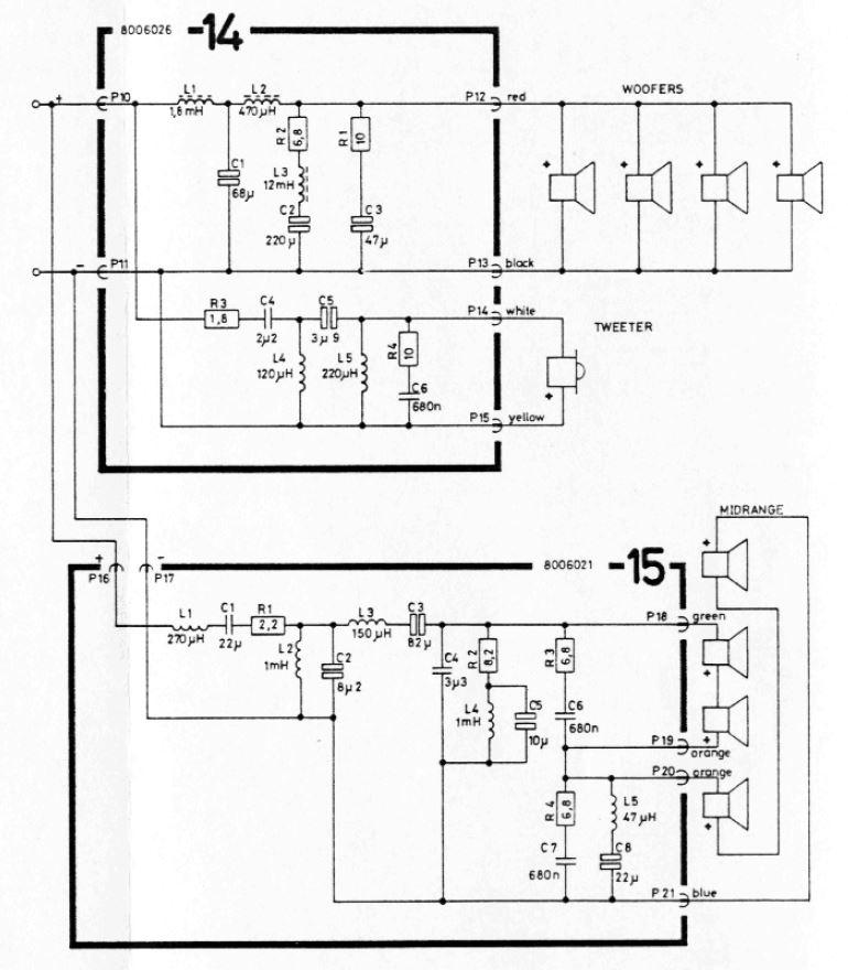
It looks like your the polarity of the drivers are marked with the “+” stickers. Check the wiring against the schematic.
If you have any further suggestions on my next step, I’m here to listen
There are spade connectors at the crossover boards. One (or more) of these may be either disconnected or misconnected. Also, many possible crossover issues could be identified if you provide pictures.
All of the drivers look to be original, which is a good start.
Glitch
… and we did not talk about the amp. Just the box.
Nice list. An addition is …
- other intentional modifications intended to make the speaker “sound better” (i.e. substituted drivers, changed cap values, etc.)
The positive news is most everything can be resolved. Pentas are worth the effort to make right.
Glitch
I assume that you didn’t have the opportunity to audition them before purchase. On the off chance that you did, do they sound different now?
Seller told me that amplifiers were re-capped, and mids have new (rubber) surroundings.
Did you get the feeling that the seller knew what they were doing for these repairs?
The first thing that I would test is the speakers and amps separately. Remove the Penta amps and use them to drive the S45.2’s. It sounds like you have already done the “BeoVOX Penta” test by driving them directly from the BM5000 amp?
Check that the all of the internal speaker driver connections are correct. You might have one or more drivers that are hooked-up with reverse polarity. You should check ALL of the connections.
I would also try to test each of the mid-ranges individually. All eight midranges should sound exactly the same. If they don’t, the refoam job was likely botched. Hook up two drivers directly to a amp (at low volume), run a frequency sweep, and listen/compare to the results of left versus right. Of course, if you have better test equipment like microphones, etc. you can run better tests.
Perhaps the crossover filter needs a recap
Maybe, but not as likely as something else being messed up.
As a note, the more detailed the explanation/description of your test/results that you provide will make it easier for people to provide meaningful advice.
…and, of course, pictures are always appreciated…
Glitch
I would have a better chance fixing it if the service information included scope traces and circuit description theory.
Unfortunately, the service manuals often exclude any “theory of operation” information. However, the datasheets for the individual chips frequently provide the needed information (or at least strong clues). It is common to see B&O using a reference design shown in the datasheet. This may or may not help, but is something else to try if you get desperate.
Glitch
July 20, 2023 at 3:34 pm in reply to: Beocord 8002: Did I get the capacitor orientation correct here? #22297Looking at the schematic, it seems sometimes the positive and sometimes the negative end of the cap goes to signal ground
I assume that you are referring to things like C2 & C204? The schematic makes sense since the “negative” lead of the capacitor is connected to a voltage lower than ground. This would keep the electrolytic capacitor (properly) forward biased.
I can’t tell if how the capacitors are installed on the circuit board are correct. Markings on the board are usually accurate, but not always. Mistakes happen in printing the boards and I don’t blame any manufacture for not scrapping boards for this kind of mistake. Same goes for printed schematics. Many times they “fix” the issue by an obscure errata statement.
The best practice is to install new capacitors with the same orientation as the original ones. Taking “before” pictures of the circuit board can be really helpful as part of the quality control or debugging process.
If all else fails, verify that the electrolytic capacitors are forward biased with a voltage measurement.
Glitch
PM sent…
I recently repaired a BC8000 with similar symptoms, a loud hum on one channel that pegged the VU meter. After debugging efforts, that were shamefully intensive in hindsight, I found a fairly simple cause for the problem…
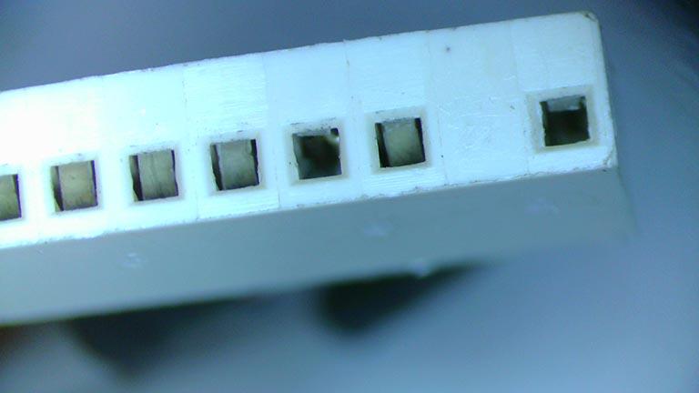
Broken pins on the tape head connector to the tape transport. Pins 1 & 4 had broken off in the connector.
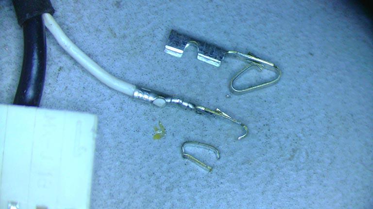
Here is a picture of a broken pin next to its replacement.
Based on my experience, I would check the connections to the tape heads for cold/cracked solder joints, broken connector pins, and broken wires before moving on to other things.
Hopefully your issue is as simple to fix.
Glitch
June 21, 2023 at 3:50 pm in reply to: Is the TC9177P IC4 a common failure on the Beomaster 6500 pre-amp? #21520That is good to hear.
Just curious, what was the cause for the “irregular volume levels on the right” channel that you mentioned in the original post?
Glitch
June 21, 2023 at 1:08 pm in reply to: Is the TC9177P IC4 a common failure on the Beomaster 6500 pre-amp? #21508Glitch, I do have an oscilloscope, will try to probe the signals, not sure what to look for though. Tested all of the grounds, all good. At this point, it might be best if i find a proper remote
Checking the DATA should be pretty straightforward (if you want to poke around while waiting for your remote to arrive). The diagrams below are from the cTC9177P datasheet.
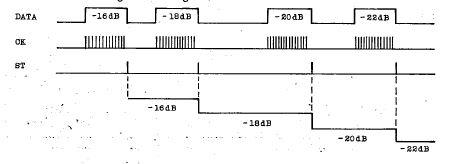
Connect the scope to DATA, CK, and STROBE signals and “single trigger” the scope off the STROBE.

Once you have a data packet captured it can be decoded with the info above. There is also a more detailed description in the datasheet. It looks like two DATA packets will need to be captured, one for the L command and one for the R command, to debug possible balance issues.
Glitch
June 20, 2023 at 1:54 pm in reply to: Is the TC9177P IC4 a common failure on the Beomaster 6500 pre-amp? #21479Do you have a logic analyzer (or oscilloscope) to check the DATA/CK/STROBE signals? Manually decoding the DATA packet will answer your “balance” question.
Are the chip grounds solid?
Glitch
Advice?
I agree with Martin’s comments. It sounds like you have the stereo equivalent of an automobile that has been “totaled”. Sure, you could fix it, but it will take an inordinate amount of time and money, and it may not ever be right again. I understand the desire to fix it, especially if the “journey is more important than the destination”.
Another possibility is to buy another BM5000 that is in very poor cosmetic condition and swap the best parts to make one good machine.
Glitch
BTW, one thing that has not been mentioned is that the lifespan of modern foam is likely much longer than the original foam. Progress in material science has advanced in the decades since the original surrounds were produced. Of course, one could still end of with bad surrounds, either foam or rubber, if purchased from a poor source.
Glitch
Yep, it looks like the BG8000 board is different than the BG8002 board. It was worth a try…
Debugging is certainly complicated by the muting relay shorting everything to ground. I don’t know the details of what you are trying to accomplish, but sometimes simply removing the relay for debugging can make things easier to understand.
Glitch
Here is a picture of the connections on a BG8002.
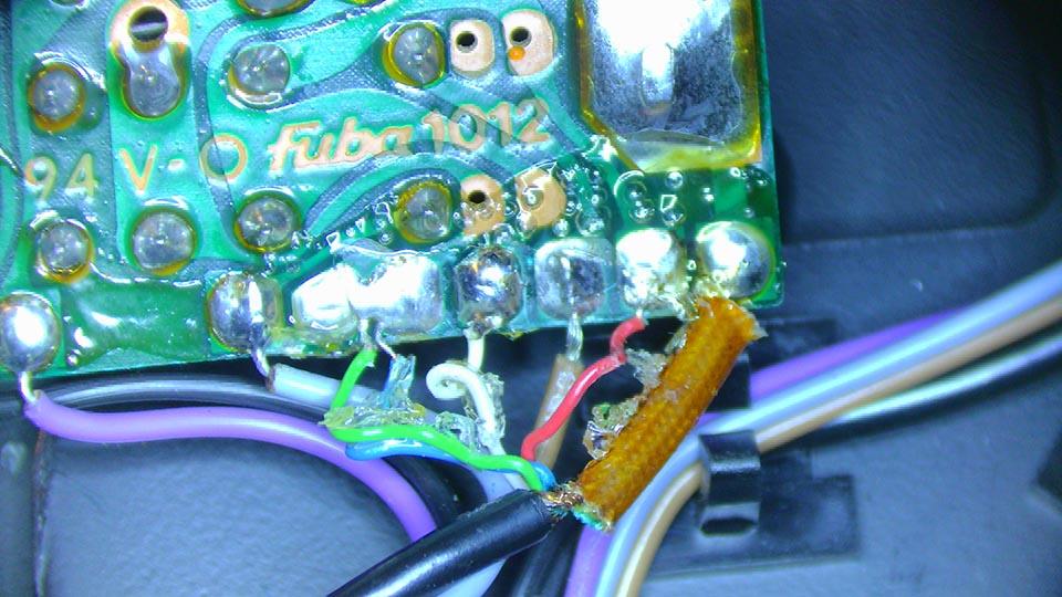
Hope this helps (and you don’t have to deal with the same glue on the solder).
Glitch
- AuthorPosts
