filip_kbh
Forum Replies Created
- AuthorPosts
-
Yes – thank you.
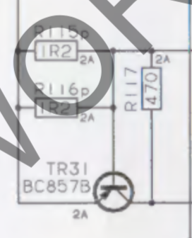
I have now turned my attention to board 10. Since I am getting 24V on P74-1 (and it should be much less – 7.8V unregulated), I am looking at TR36, and it is not working properly, so I will have to replace that.
However, it puzzles me that there is seemingly a short on the board. TR31 measured a short, so I took it off but even without the component, I still measure a short 🙁
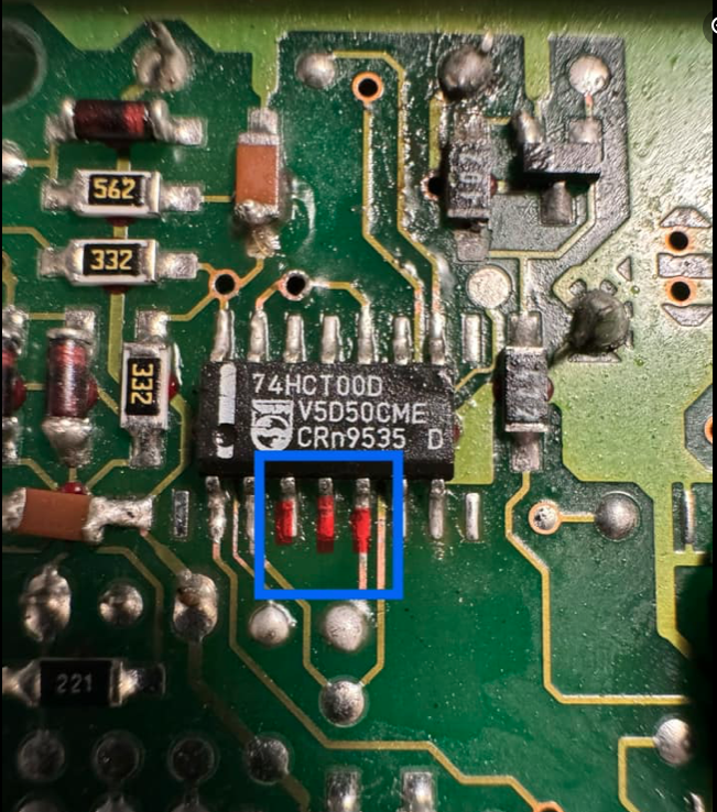
Turns out the three pins get the same signal but there was a broken trace under the IC.
Hmm – these three legs are shorted. Am I right in assuming that they shouldn’t be? It’s pcb3. When the board is not connected, the BeoCenter starts up with two relays and the tape motor kicks in. The chip is right under the battery damage on the other side, so who knows what’s underneath of great surprises.
Can someone please upload a clear, zoomed in picture of the cpu board front and back? The service manual scan is not very clear.
I think there’s still an issue with the micro processor board. I realise I made a mistake repairing the dead track but now that it’s fixed to the right points, there is no relay clicking. I did experience that some of the panels lit up but I don’t know what I touched prior to that. Argh.
When the motor is spinning, pin 3 gives 15V – but it is not every time the plug is plugged in that the motor will start.
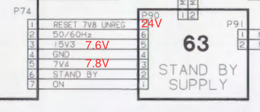
After changing the three diodes on the standby board plus fixing the trace on the processor board, the tape motor now spins but that is all. I still don’t know why I have 24V on pin 7 when it should be 7.8V. My measurements in red below. I am also missing a 15V supply.
Yeah those batteries can make a mess. I don’t know if it is just the picture, but it looks like there is a crack in the diode D5
Indeed, it does look that in the pictures. I have just re-opened it and tested D5, and there is no crack, and it measures fine. But thank you – because I originally forgot to test that diode. Now, off to my favourite all too expensive diode pusher.
I guess I should have started by checking the battery:
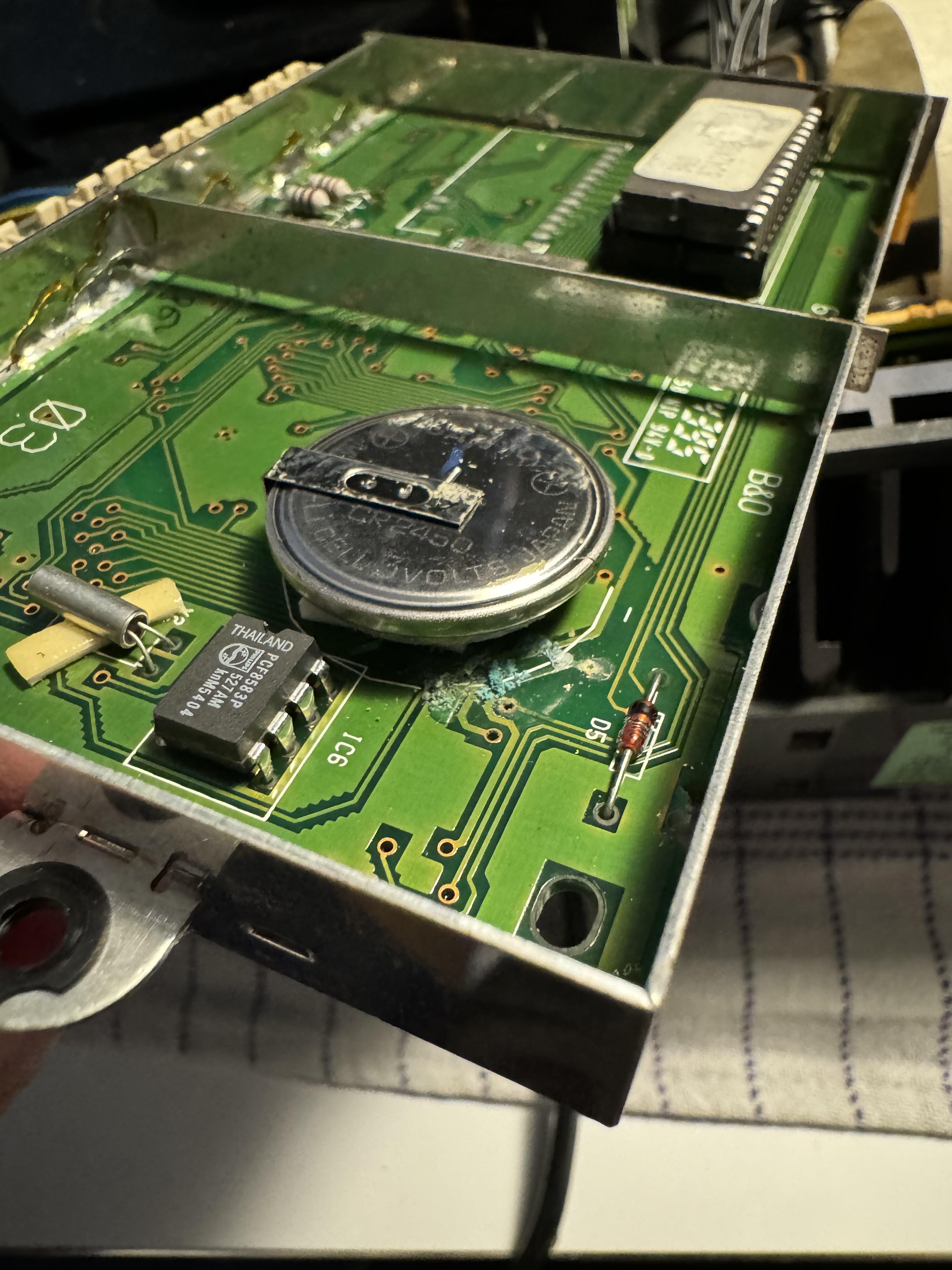
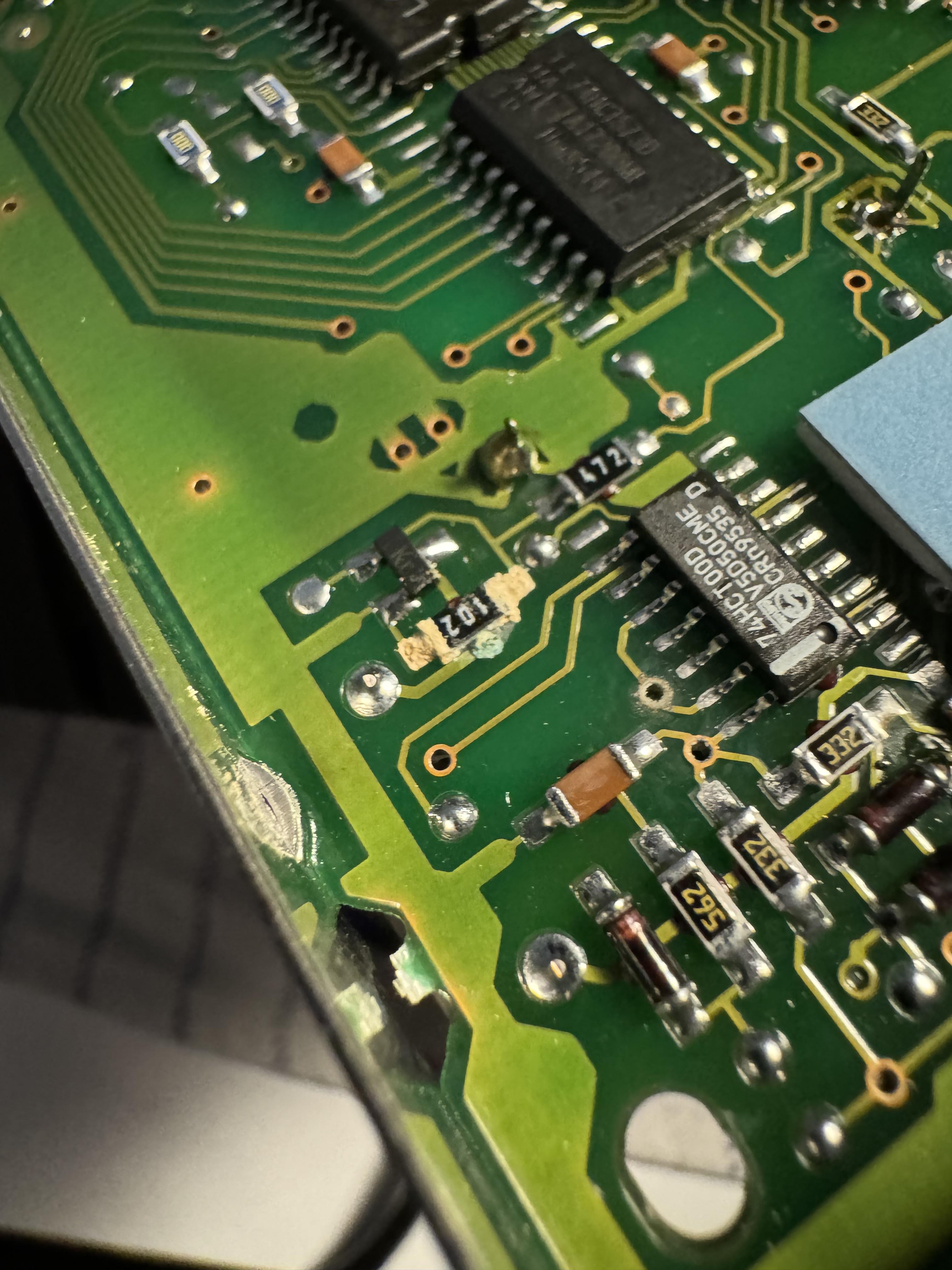
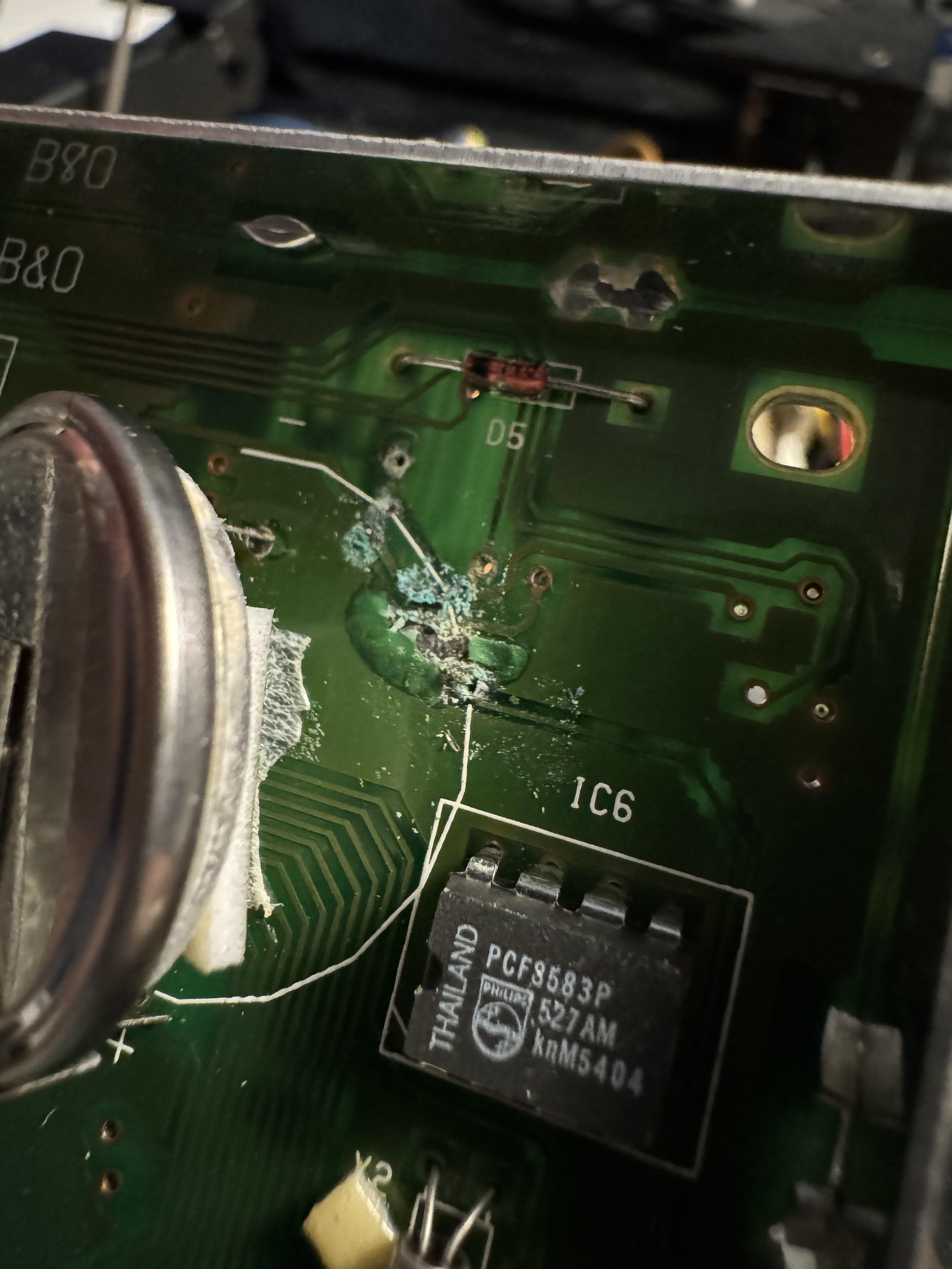
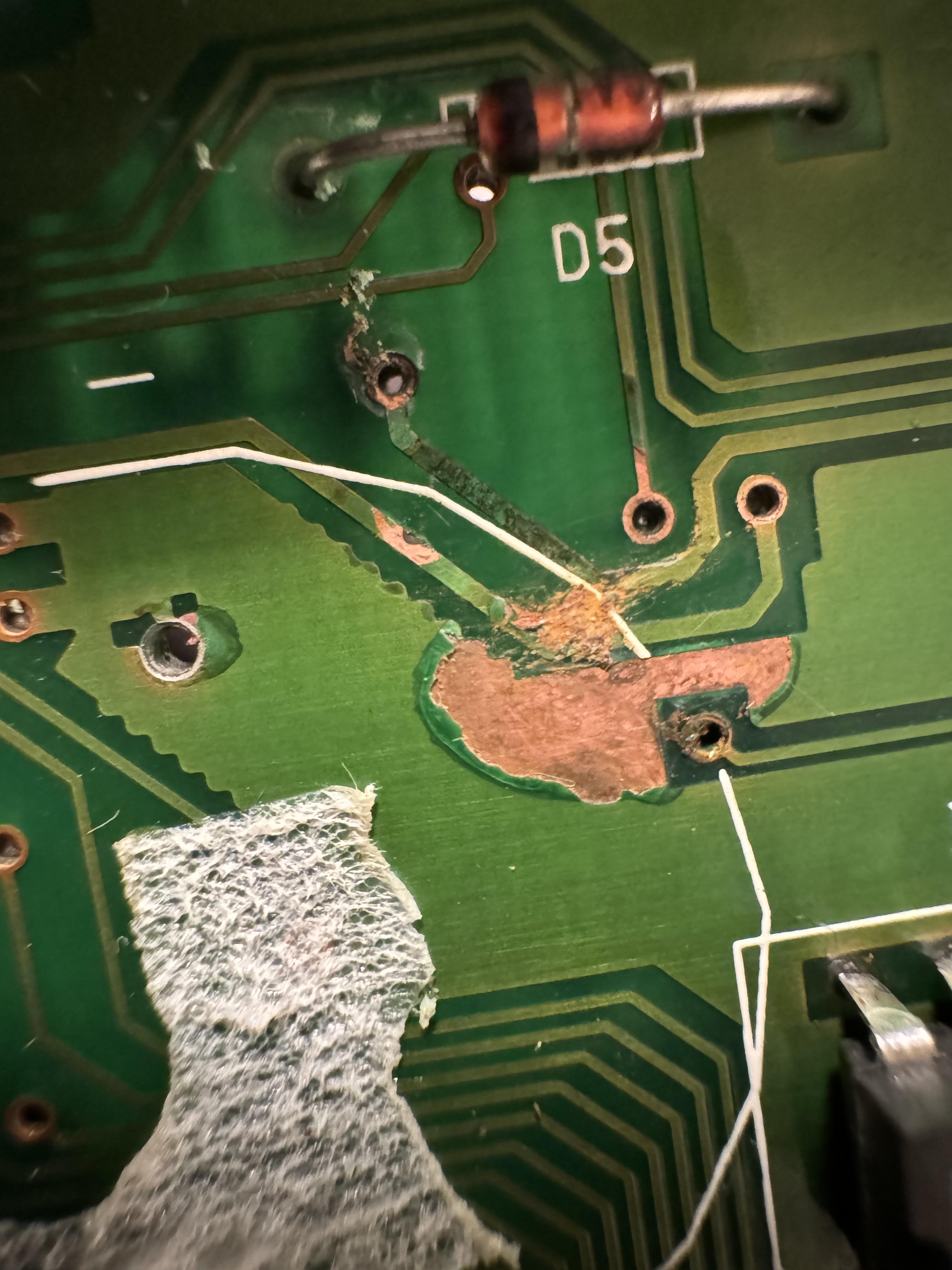
There was only one trace that was broken, so I fixed that. Those batteries are a ticking time bomb ?
All fuses were good.
.
Is the relay on the standby board supposed to click? Because mine doesn’t say a click.
I have the correct voltages from the transformer. On the standby board I also have correct voltages except for P90 pin 1. It’s supposed to be 7.8V as I read the schematic (it says ‘7V8 unregulated’) but I measure approx. 24V.
Update: D31 was faulty. After changing D31 and R54, the carriage now behaves the way it should. Nice!
Regarding the motor: it also started working after I pulled it apart, gave it a drop of oil (yes, I know it will not last forever) and changed the order of the small plastic discs.
Now the deck was working kind of great – however, the 45RPM was not stable, and when I tapped the board with the speed relay, it would lower the speed significantly.
So, I decided to take a look at the National relay. I cleaned it with a fiber pen and put on the plastic lid again. After this, the motor only spins one second – and I am not sure what to do.
Looks like resistor 1R54 is defect as well as TR17.
Depending on the cost of shipping, I may be interested in the front panel (the one that can open and covers all the secondary buttons). I live in Copenhagen, Denmark
Should be fixable. But why was it overheating in the first place? Idle current may have been set too high due to corroded trimmers. But as there are parts that actually burned, I suspect a short-circuit may have happened. I am sure other experts here can tell you what happened.
Start with cleaning the board with a clean paint brush to get rid off all the dust.
The damage seems to be only in one area of the board. Find out what the shared denominator is for those four parts to burn up. Then order new replacements. When desoldering on this board, do not use too much heat as you will lift traces. Also – was the transparent plastic holder for the filter capacitors missing, or did you remove it to take the pictures?
First, check the fuse(s). There is one where the power chord comes in (you need to unmount the bottom of the amp. I don’t remember if there is more than one fuse.
I would probably test the fuses first. The fuse holders are known to tarnish, so they will not make any connection. In that case they can be cleaned up with a fibre pen. Also, please take a look at the schematics to see where the source lights get the power from and which voltage. Measure it, and trace it to where it stops.
I would suggest cleaning the laser lens and the mirror. You need to open the lens to do this. There is a video in the thread Fixing Beosound 9000 laser.
- AuthorPosts
