Evan
Forum Replies Created
- AuthorPosts
-
Ok so I’m officially up the creek with only one working tweeter at this point. Being the time-impoverished individual that I am, I leapt up from my workbench and into the car. Drove up to the office to rummage around for some tweeters that might hold me over until I replace the fried one with another original SEAS unit.
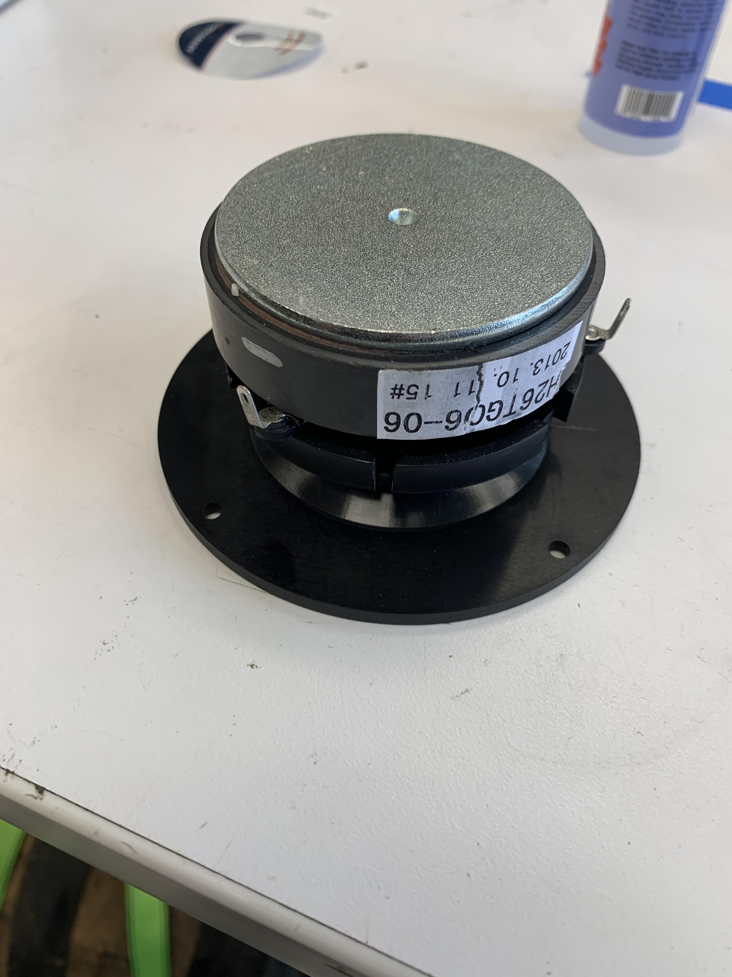
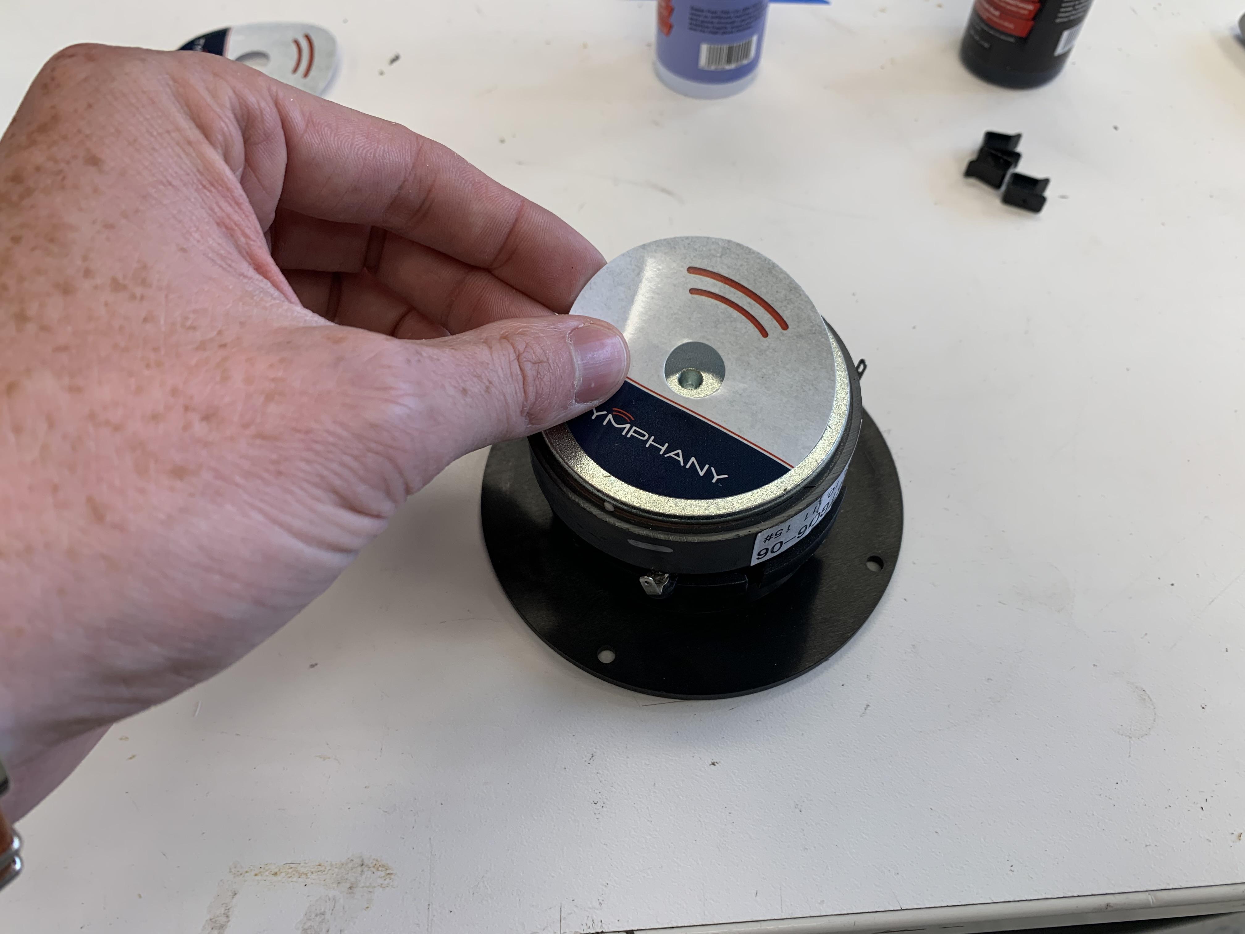
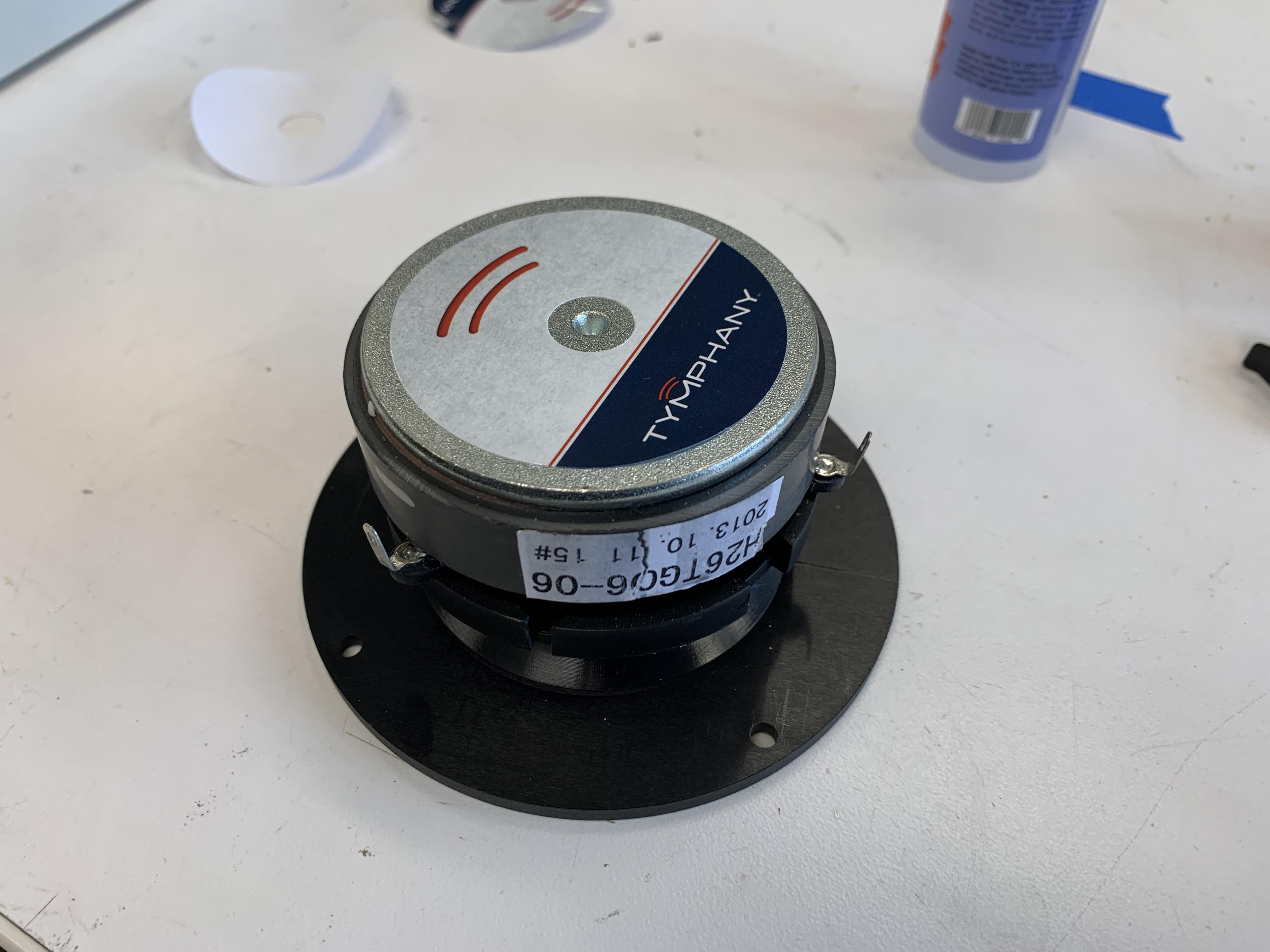
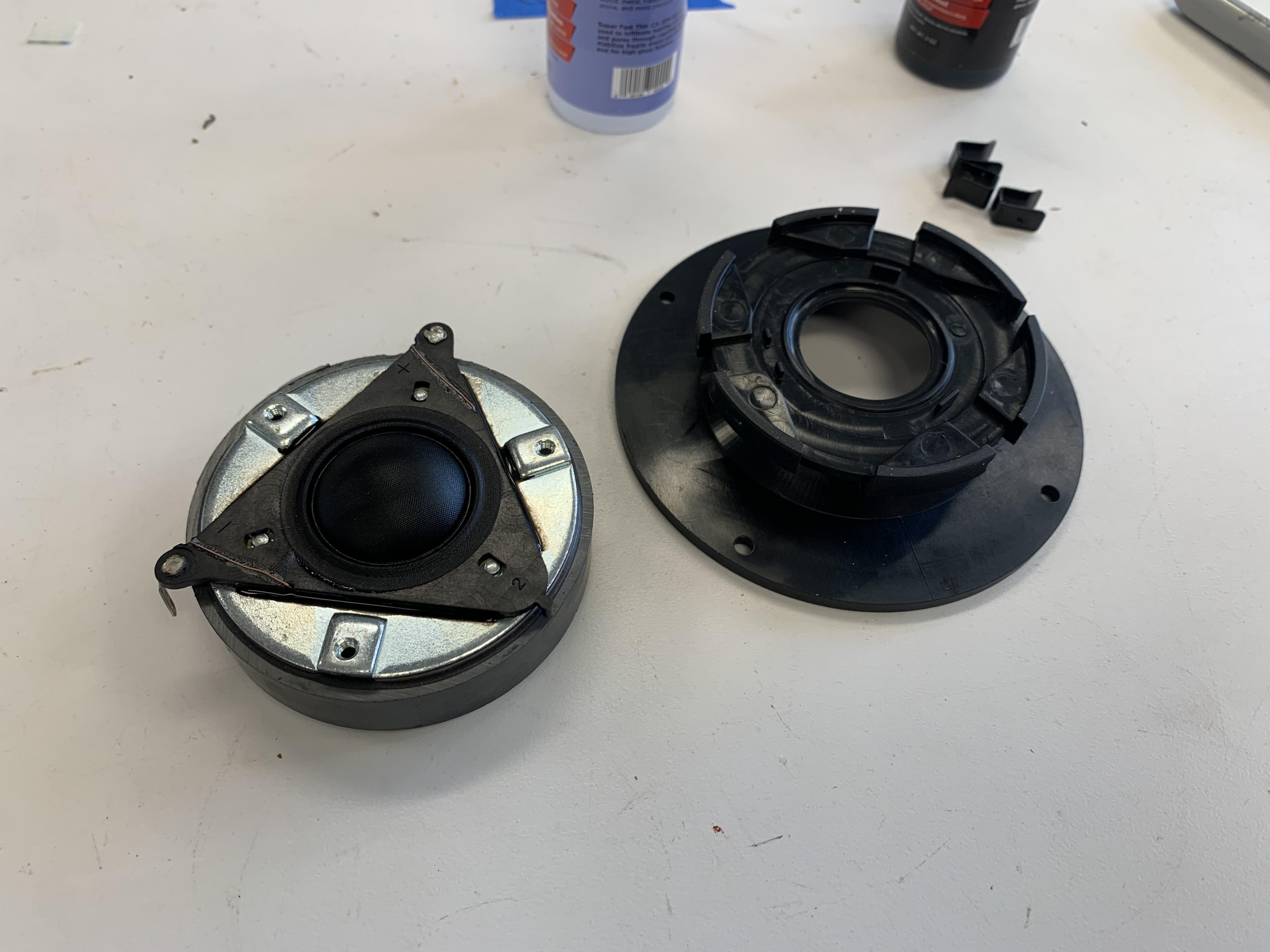
We seemed to be overstocked on these [very old build] H26TG06-06 units. These are almost completely unmatched in every way from the originals acoustically but they are an epic tweeter overall. I had to take the waveguide off of course and add some branding because stickers make everything better. Also had to glue down the butterfly as the clips that hold the waveguide on also secure the butterfly.
Wonderful thread Evan, congrats to a very nice work, looking good
Cheers, Soren! Thank you very much!
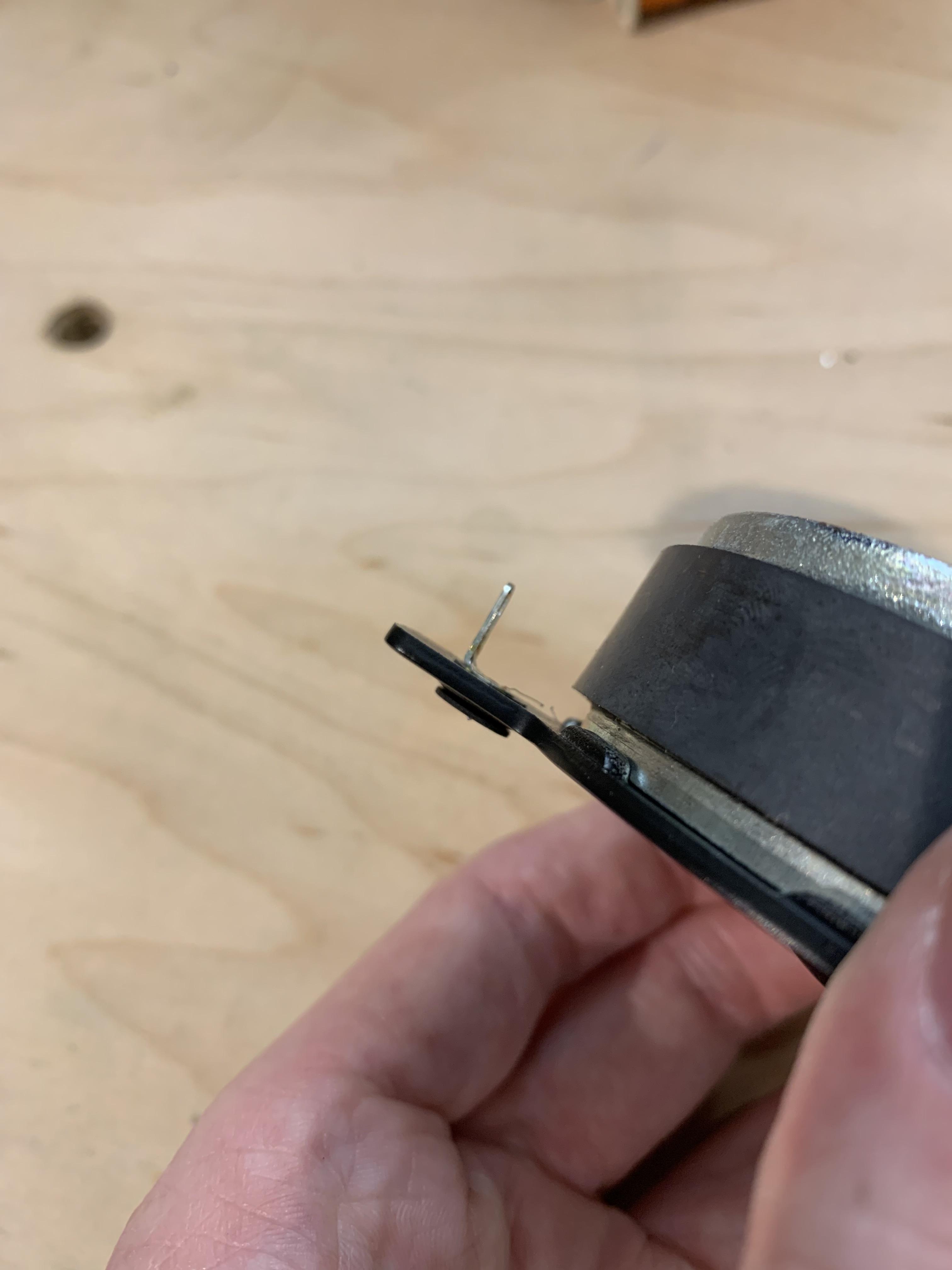
I attempted to solder the broken lead wire but unfortunately it is coated so nothing stuck to it. Next path was to take the butterfly off and take a turn off the coil and unwind some fresh lead wire. Sadly some more bad evidence of restaurant thrashing was hidden inside.
I think someone cooked this coil a little too hard! The coil was loose in the gap and had come off the former!
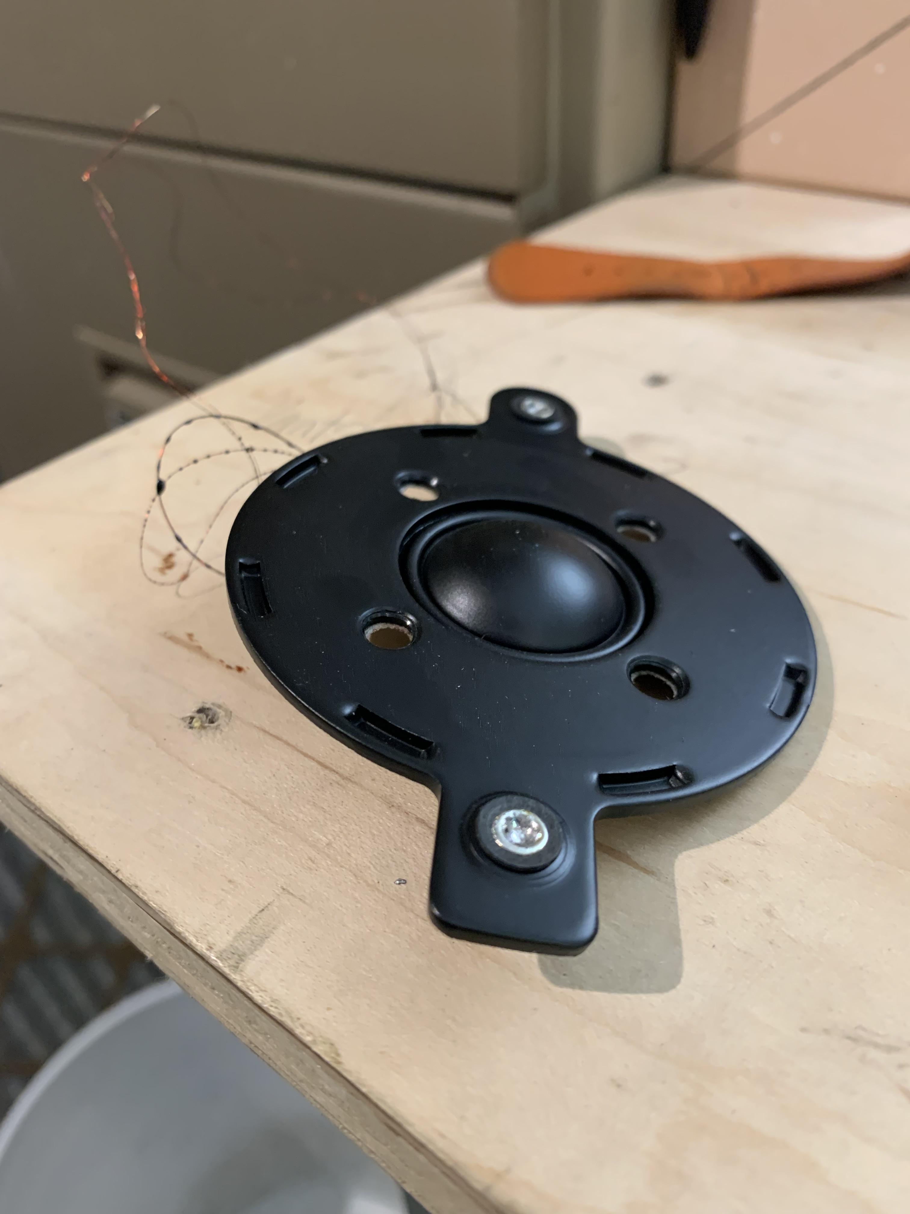
Now its time to talk tweeters. As I mentioned earlier on, one of them was making zero output.
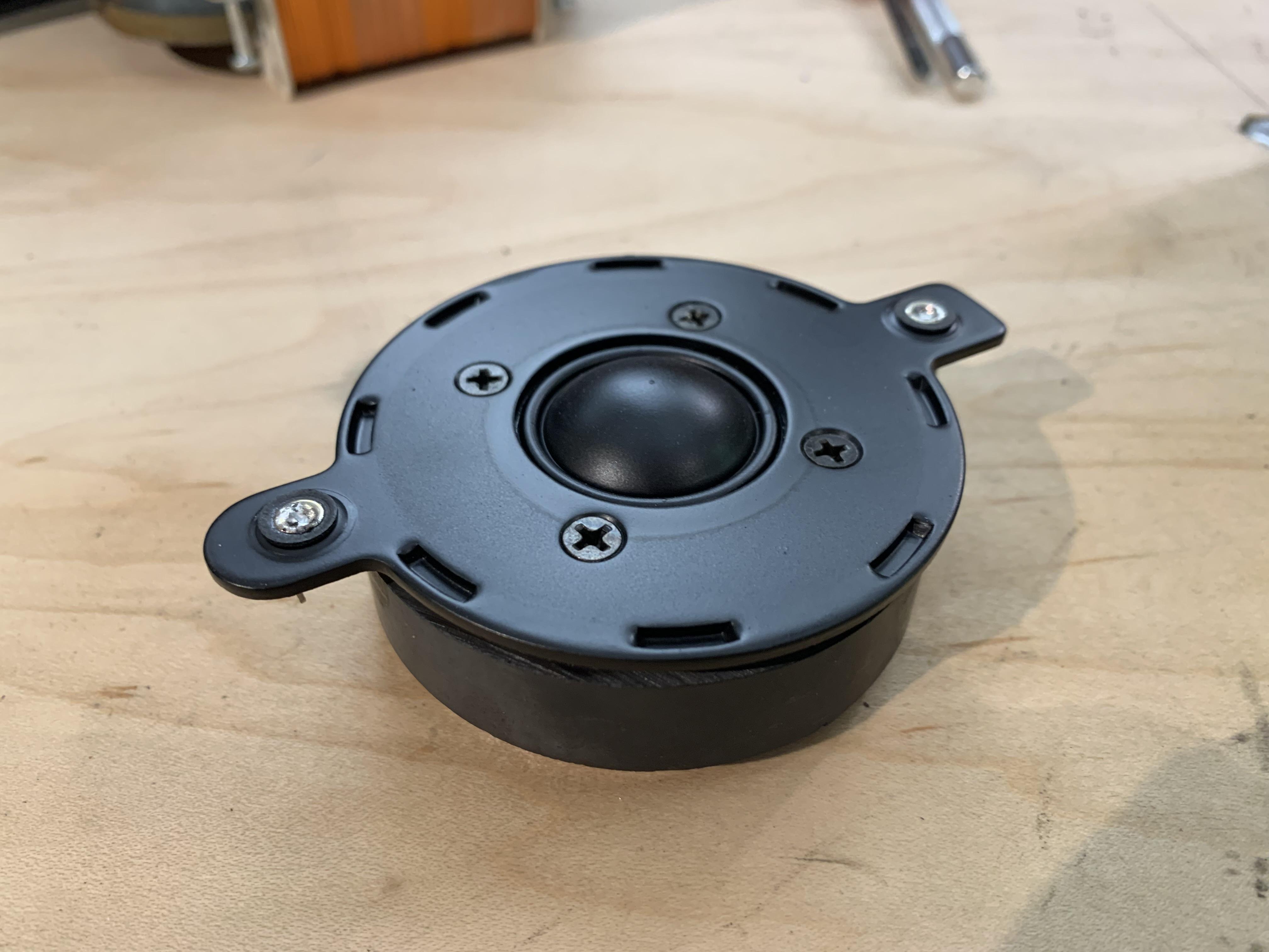
One of my eagle-eyed colleagues noticed that the lead wire was broken. The coil measured ok (from the broken end) so I decided to do a repair.
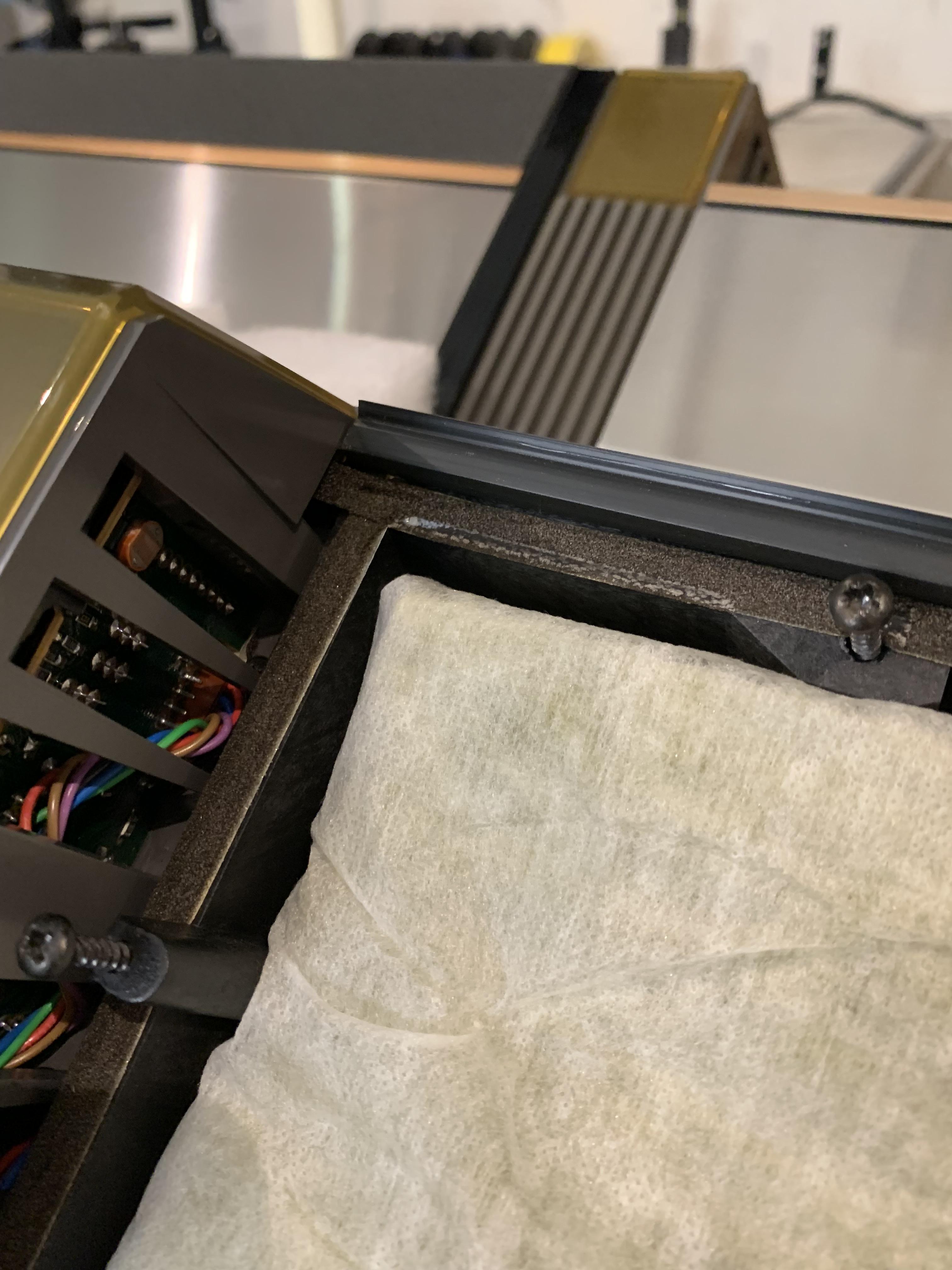
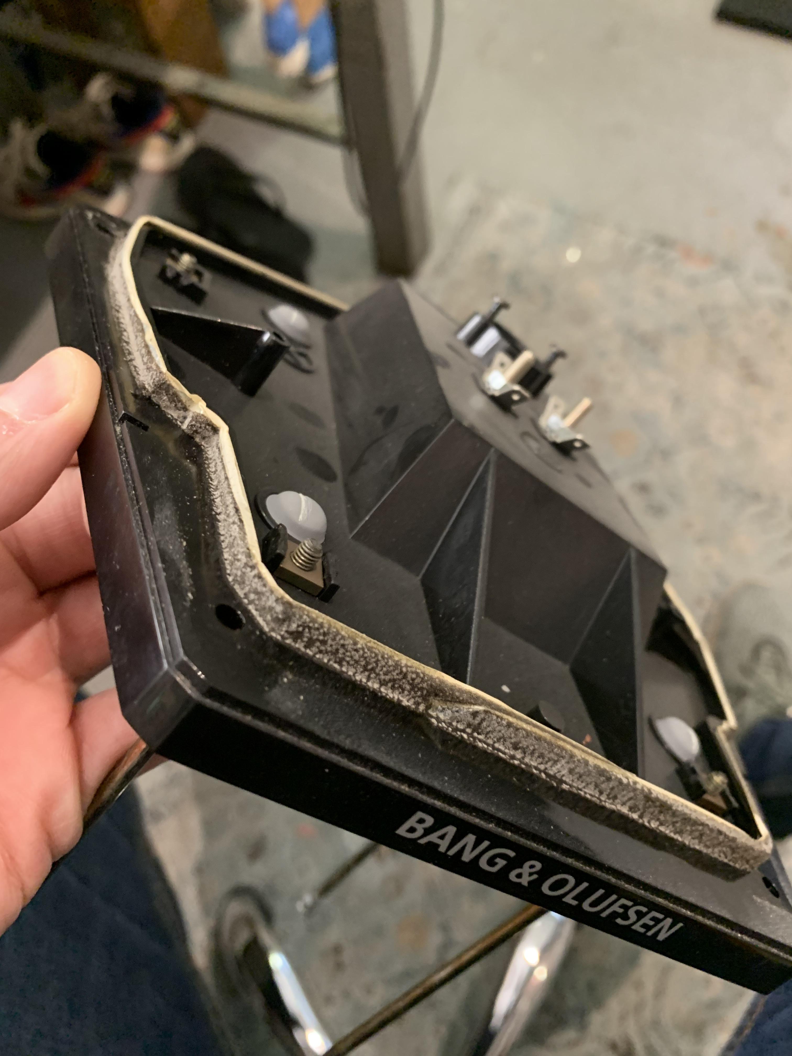
The worst of the sealing issues I found was actually around the twee-mid baffle edge. The foam is predictably rotted and without any life left however that wasn’t the worst part. Whoever assembled this foam tape originally back in the day completely missed the actual sealing edge / contour of the baffle. This is effectively an acoustical “short circuit”.
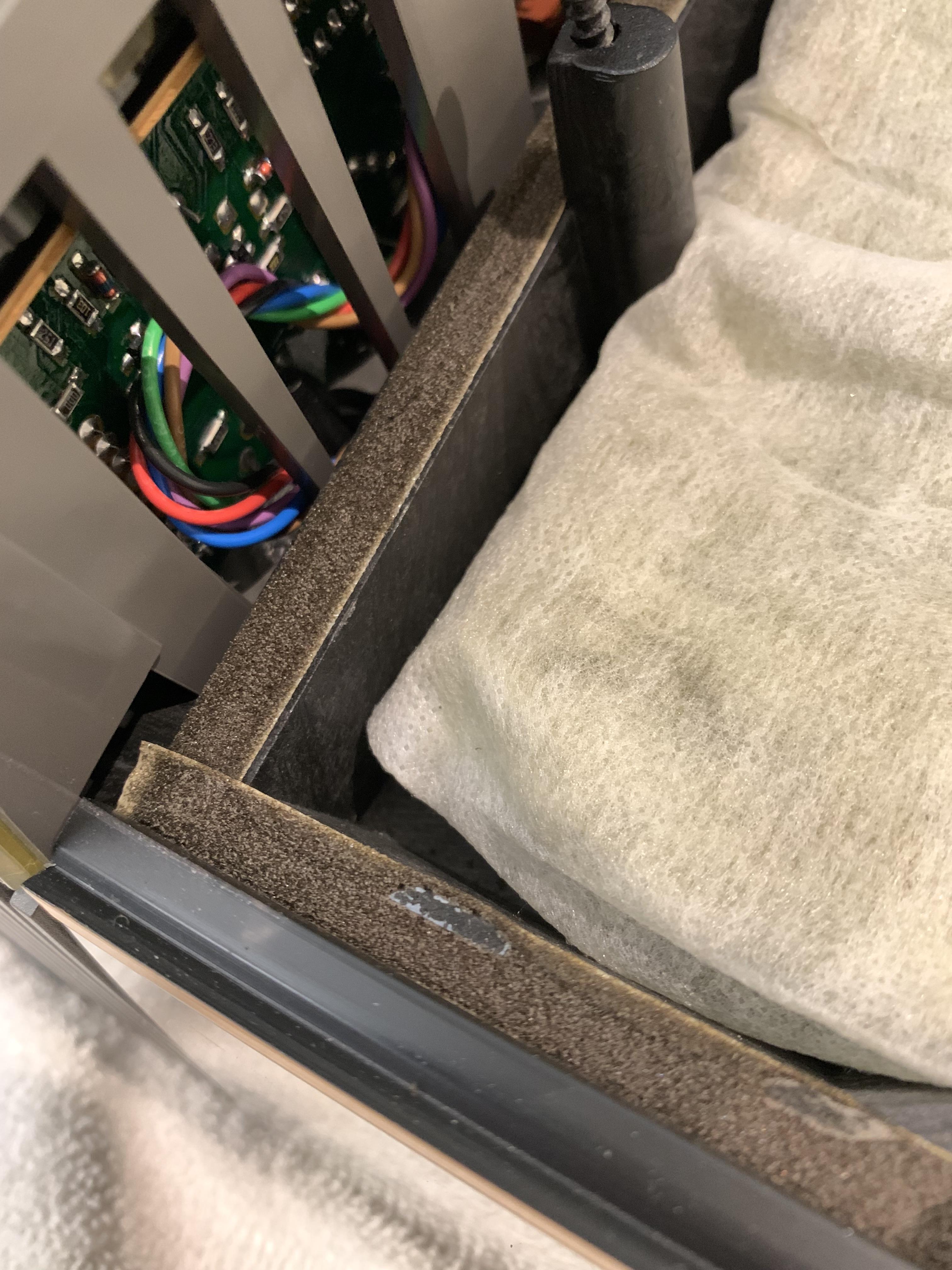
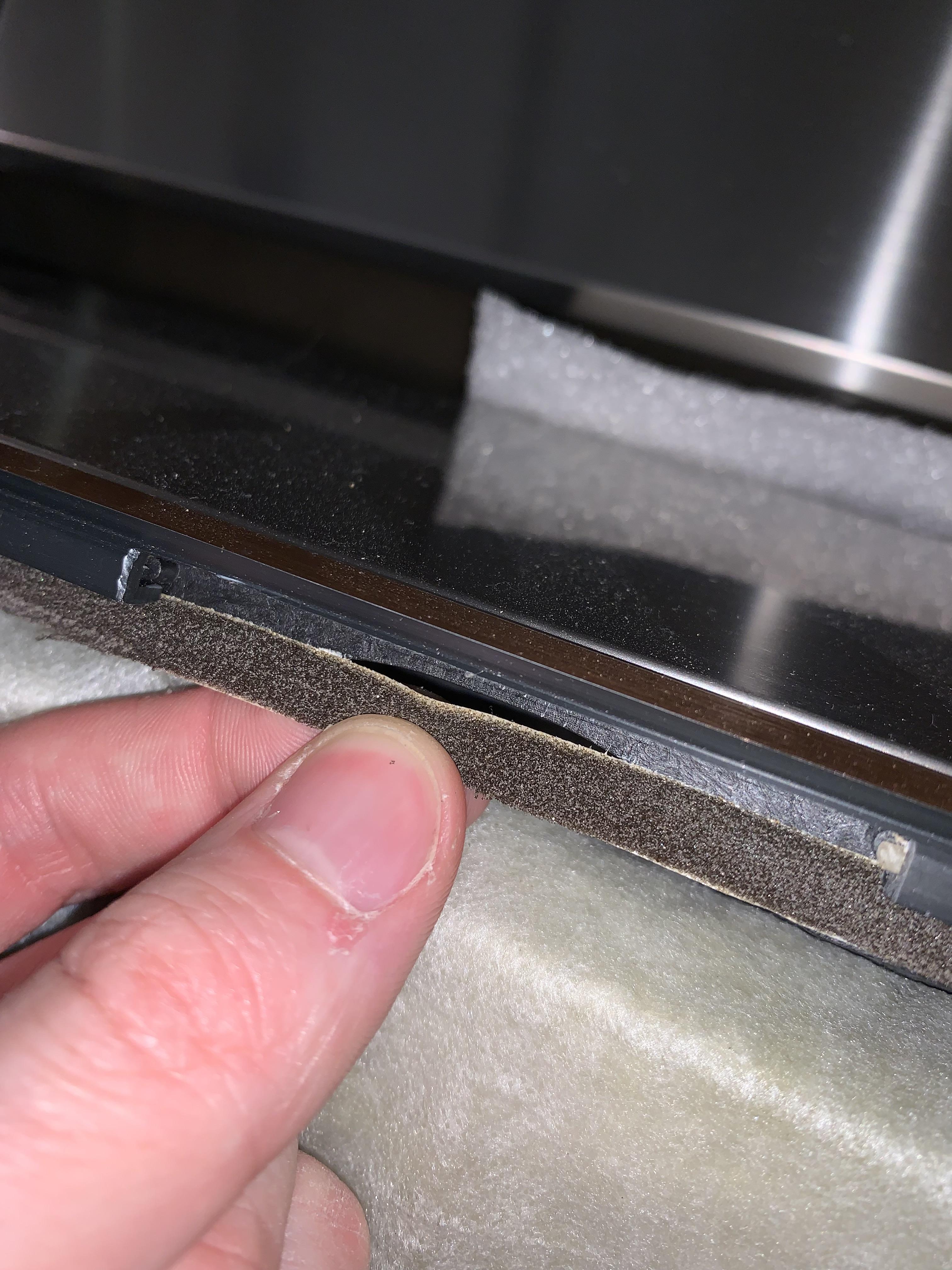
Here is another great example of deteriorated foam. This is the base of the lower woofer cabinet, I also replaced this on both speakers.
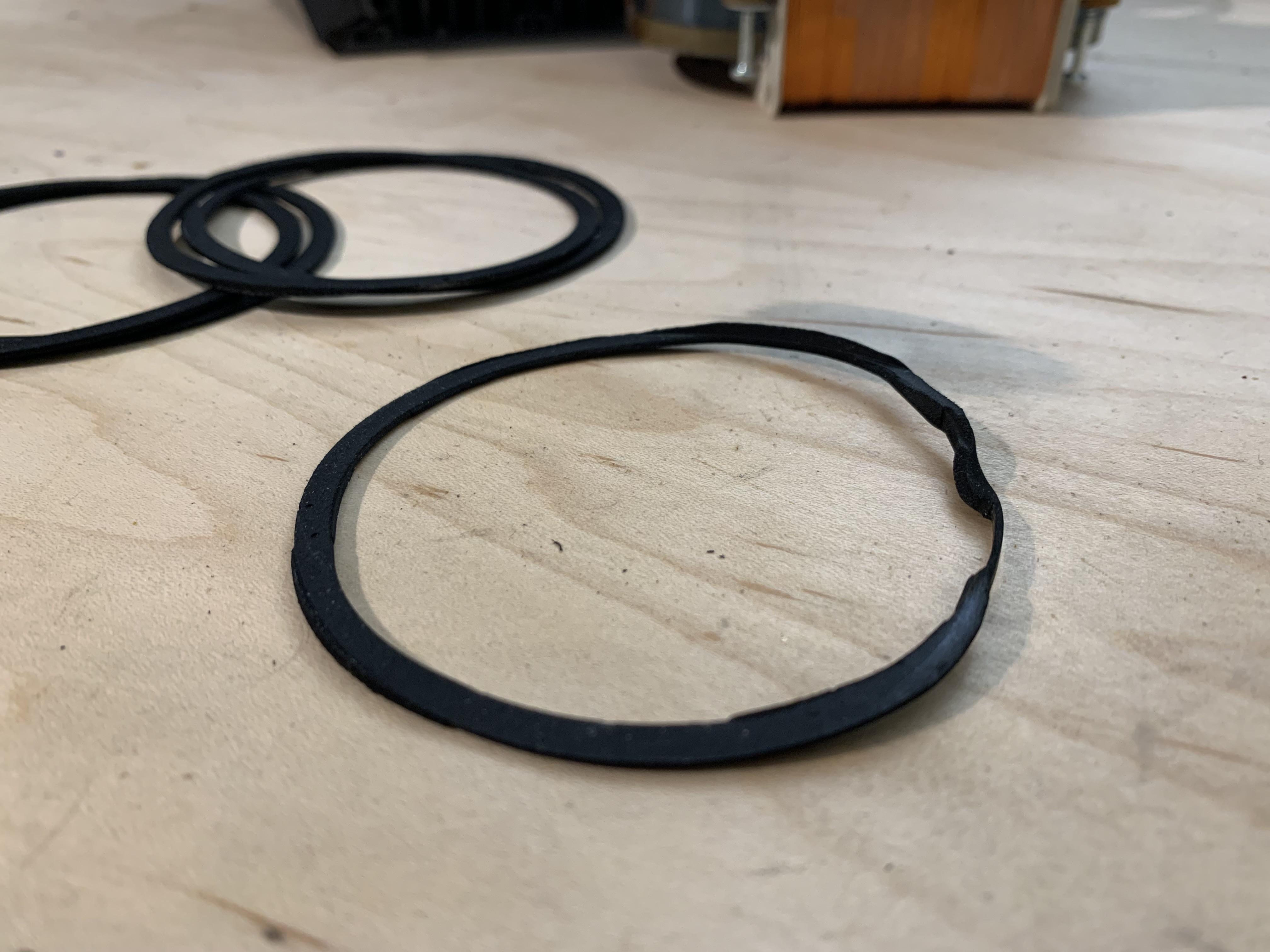
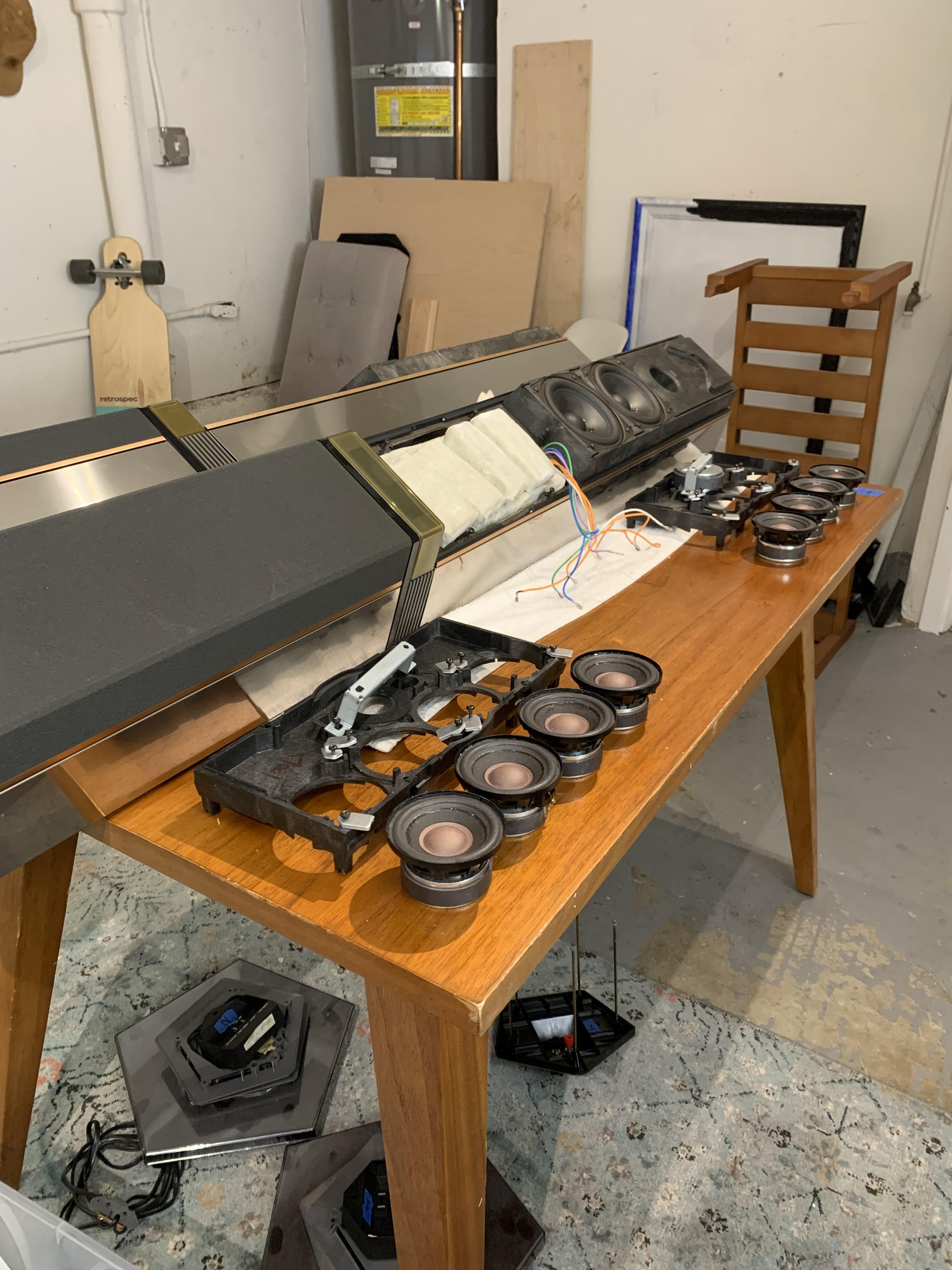
Before we put those mids back in, I noticed something that needs mentioning. The gaskets for the mids looked reusable except for one. One was not properly installed in the first place and was too messed up to re-use. I ended up putting on new foam gaskets myself for all drivers. Adhesive foam strips work well for this sort of thing as they can’t move out of the way during installation.
Sealing is an important topic and I suggest those of you reading this to take a closer look at old gaskets and seals in your speakers. Leaks (even small ones) can lead to strange noises and buzzes etc. Most of all they lead to the acoustic system not working/performing as intended.
Now safely back at home, the mids are ready to go back in!!
Things were going well. ….until they weren’t! The outer flange of the surround was starting to wrinkle and not lay flat so I frantically ran around to try and find something to hold them down while the glue set. Luckily we are a well equipped office and have drink vessels of the exact-right size for this job.
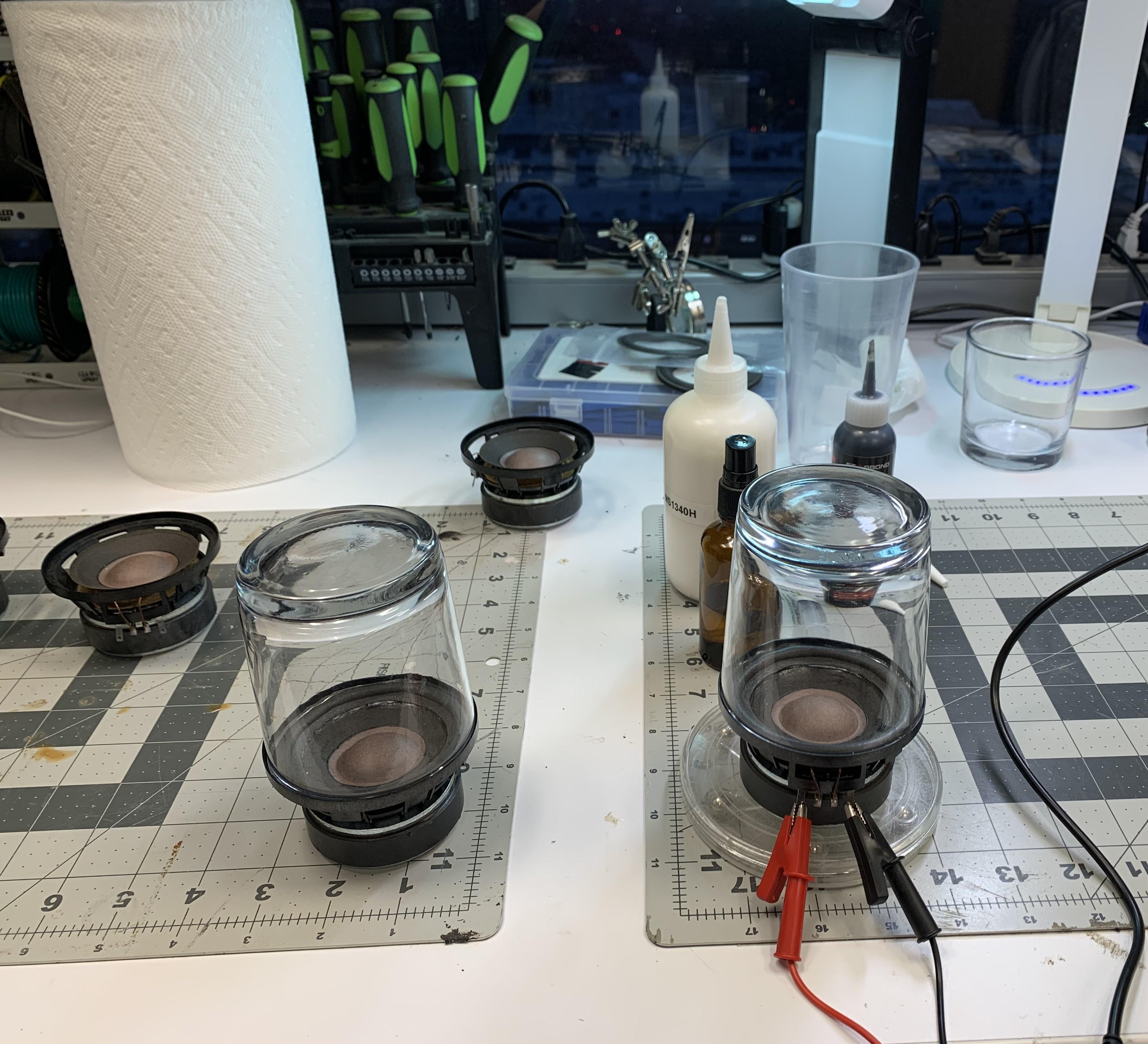
While the glueing-up was taking place, I also made sure that I ran some signal through them to ensure no nasty misalignment and coil rubs were to take place.
One of my favorite view from the office. We are very fortunate that our company values engineers and doesn’t shove the soldering station in the basement somewhere!
This is usually just our random electronics area. Soldering, buzz-up station, general debugging typically goes on here.
Working in a speaker company means we usually have all the tools for the job haha! In this case it was nice to have a small turntable to spin the drivers on when applying the glue for the surrounds.
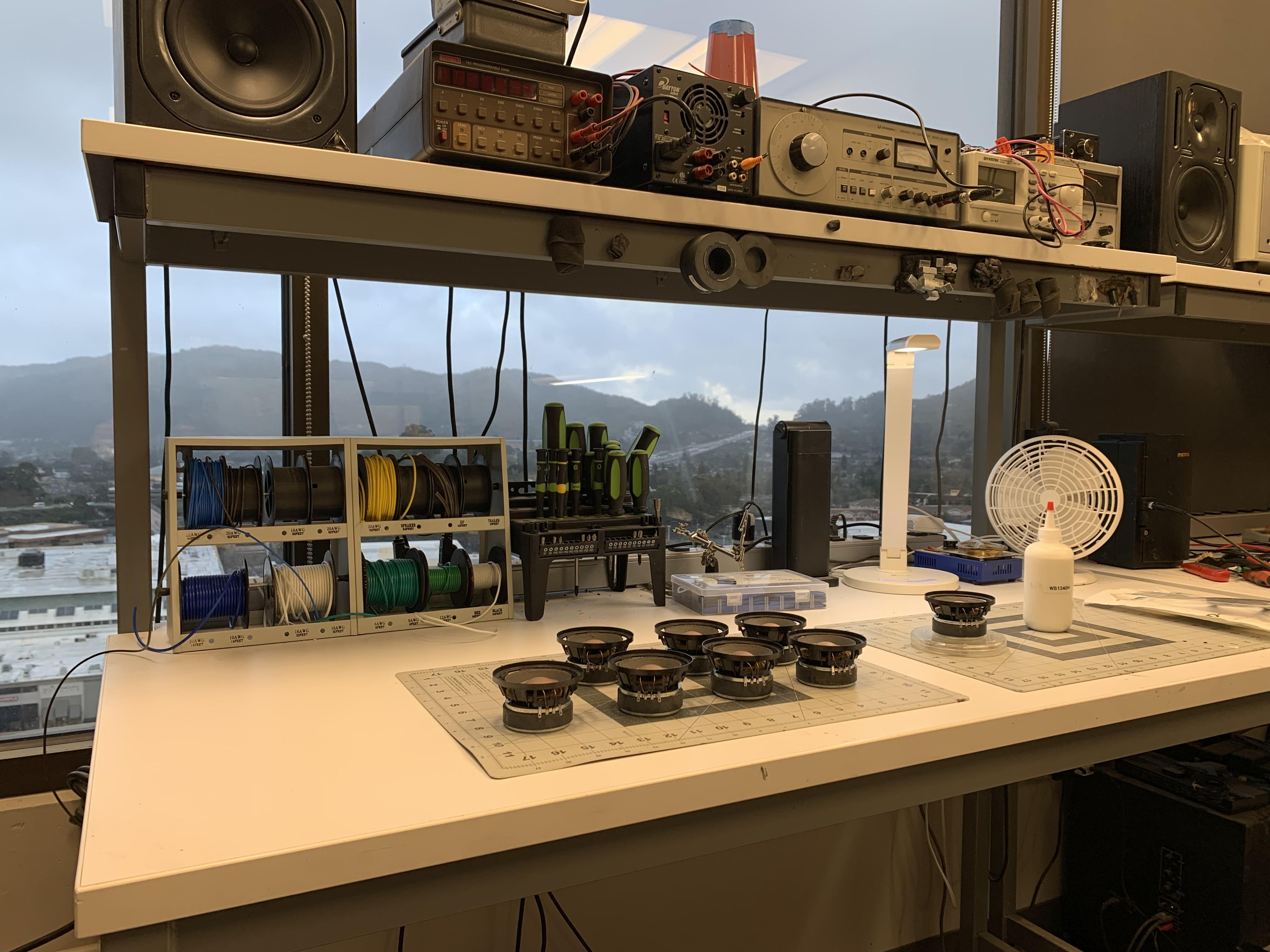
We had a long, three-day weekend here in the US and everyone but myself cleared out early on Friday. After everyone took off, I connected my phone to the monitors on the shelf, started jamming and getting on with the work.
About an hour or so later, I have a full set, ready for the re-foam job.
After swapping out all the parts in the amps, I also set the bias voltage and DC offset and called it a day. They seemed to be tip top!
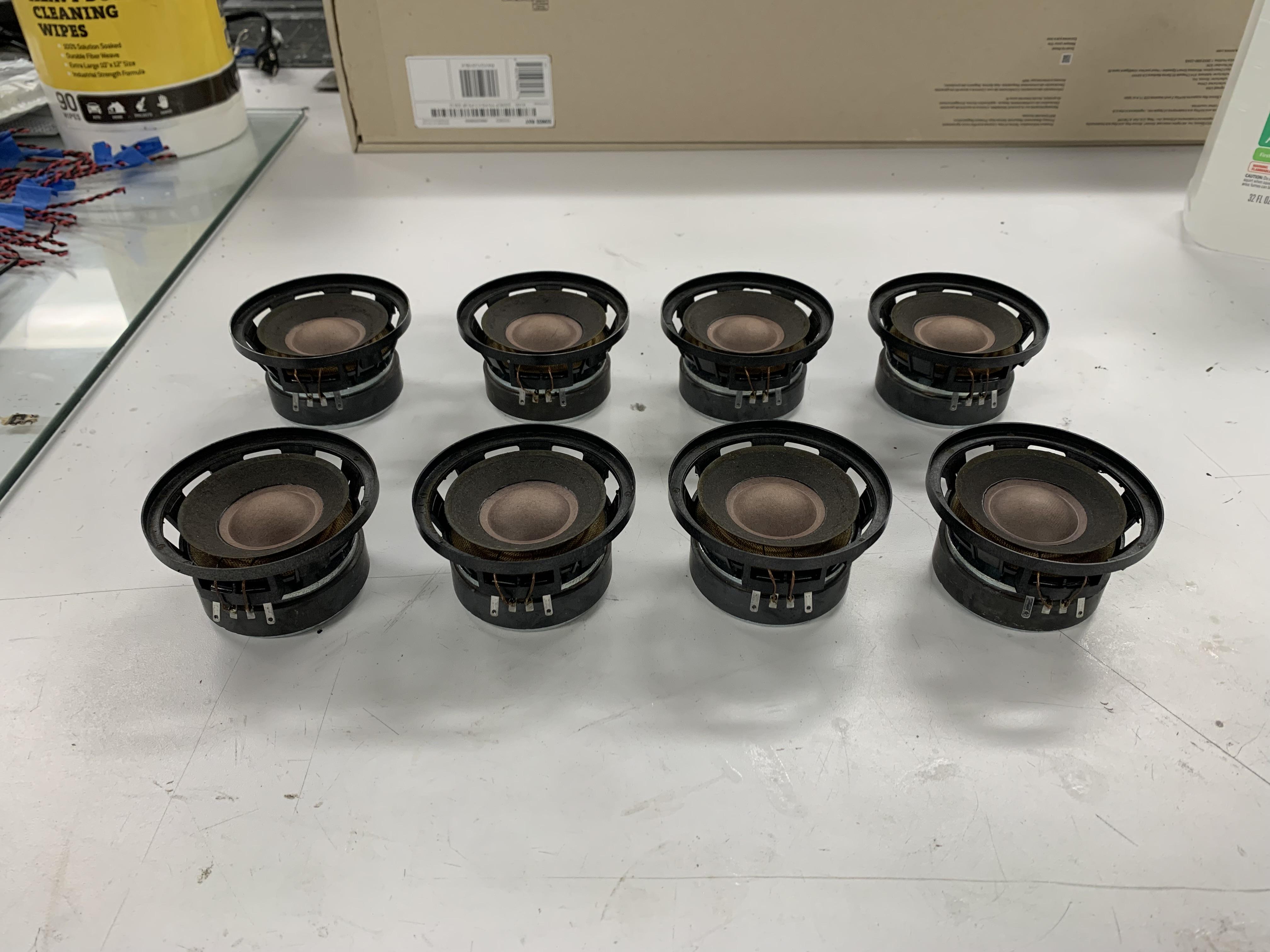
Now to switch tracks a bit and get over to sorting the acoustics. Classic Penta story here – all eight midrange transducers need new foam surrounds.
This particular chapter takes place in the office lab. A lab where new loudspeaker prototypes are brought to life so it is the perfect place to do this kind of work.
Starting with a shop vac, I carefully vacuumed up the large chunks that were basically just falling off. Then alcohol to remove the remaining residue in preparation for the new surrounds.
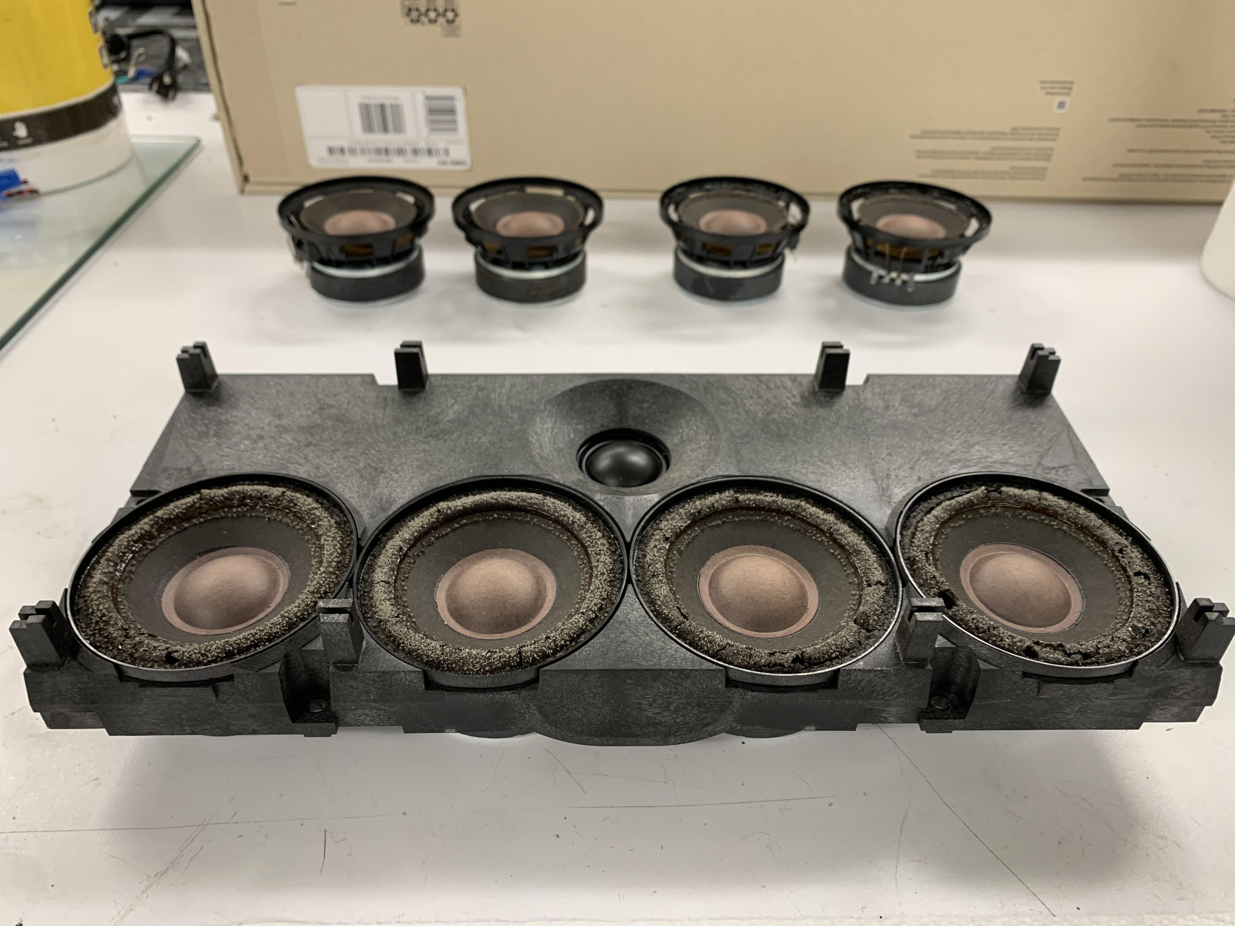
I’ve never seen such terrible foam rot before!
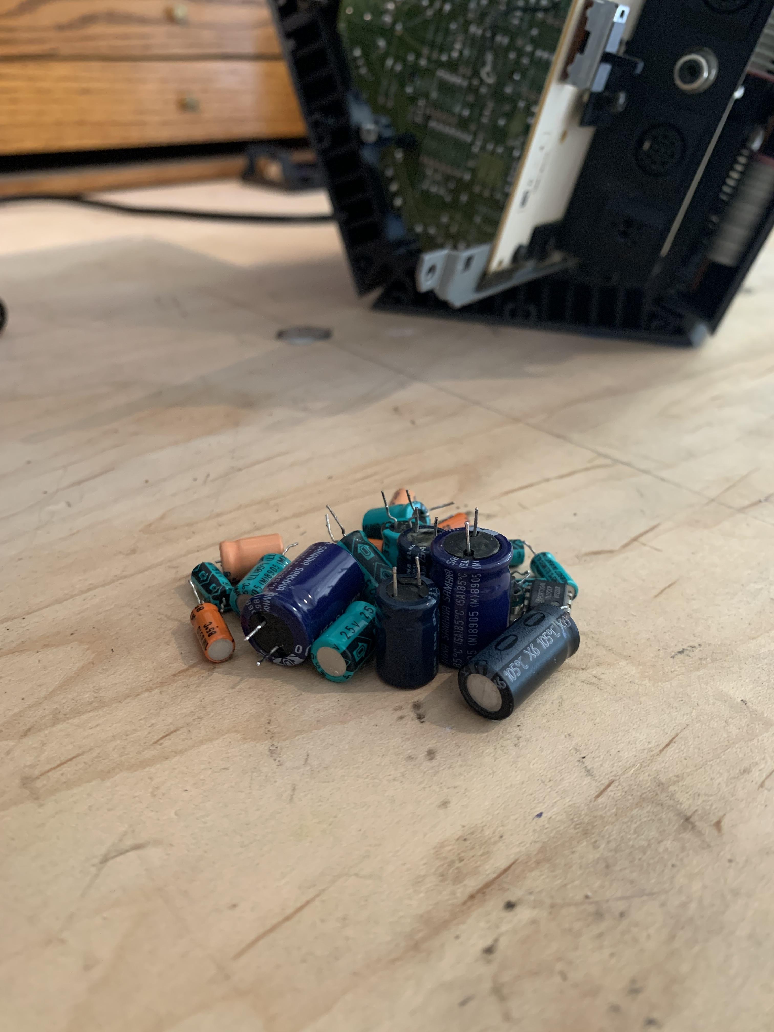
After a few hours, I had a modest pile of old caps out and replaced with fresh electrolytic goodness.
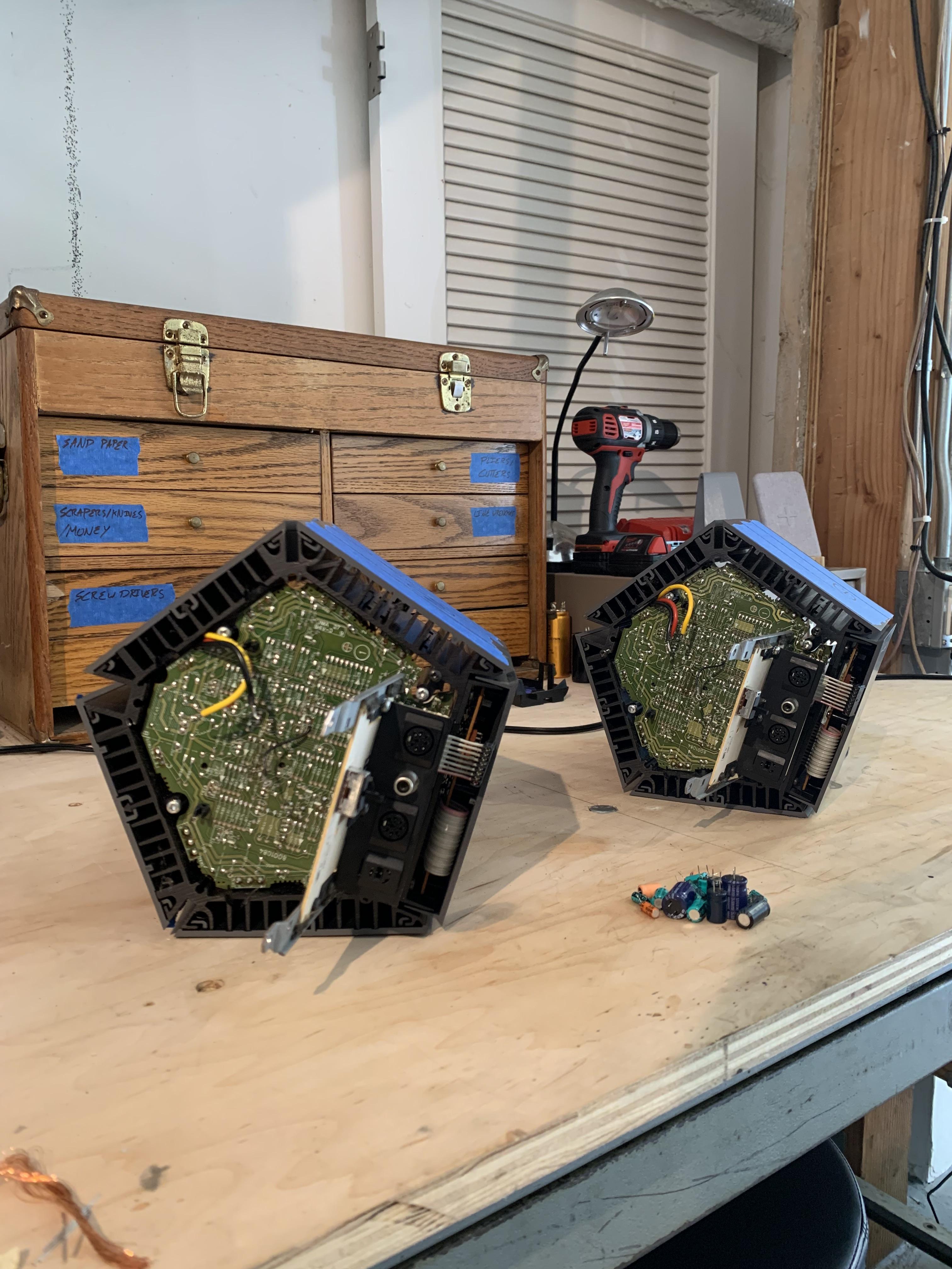
Again – absolutely amazing opportunity to marvel at some truly epic packaging / design engineering.
Now for all the little caps inside plus trimmers and a fresh Burr Brown OPA134 op amp. Hope you like working with a flashlight.
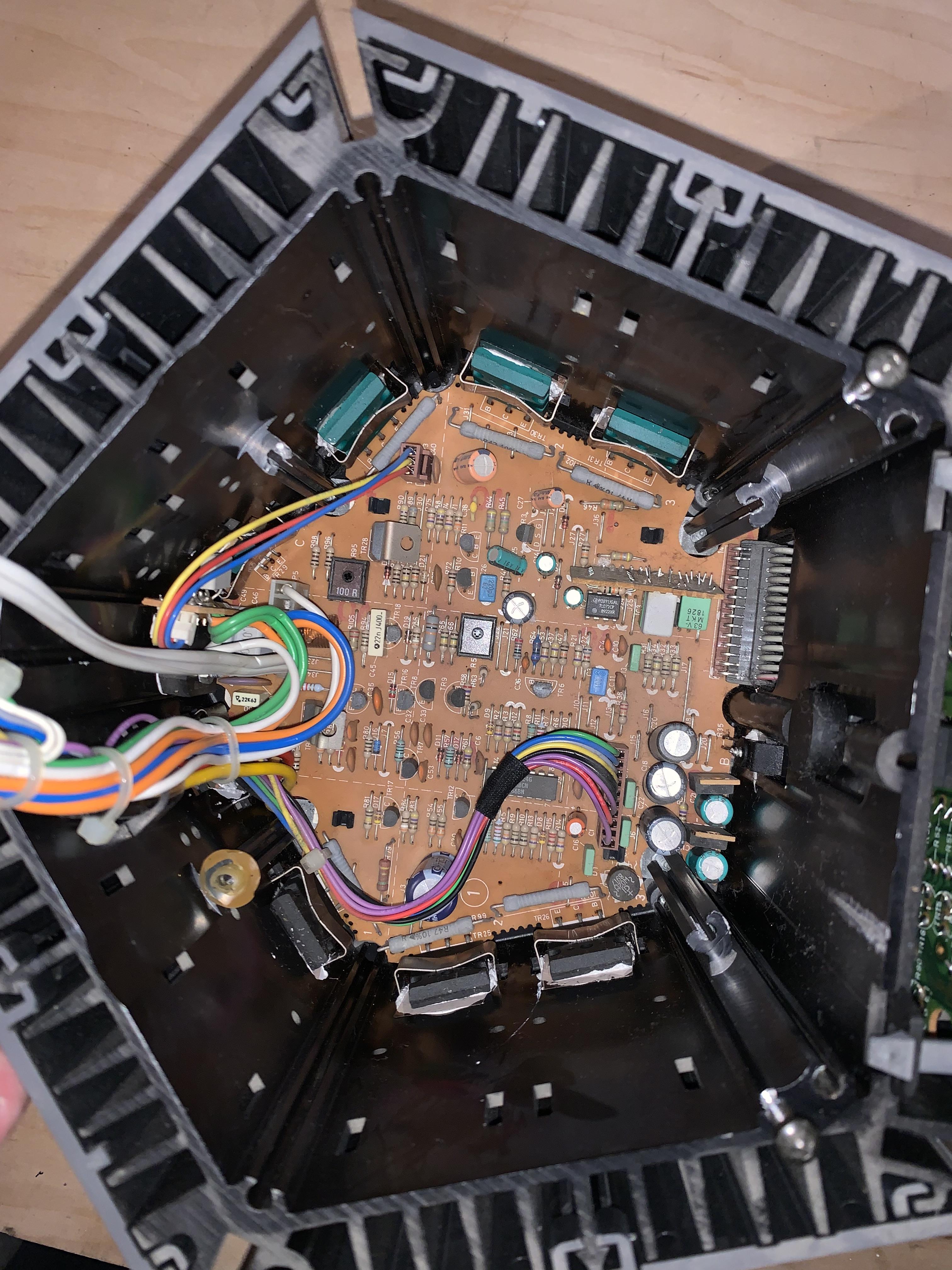
New power caps are finally in. I always appreciate finding all the little B&O branding elements throughout old systems like this. I’m guessing these were all made by suppliers but still nice to see.
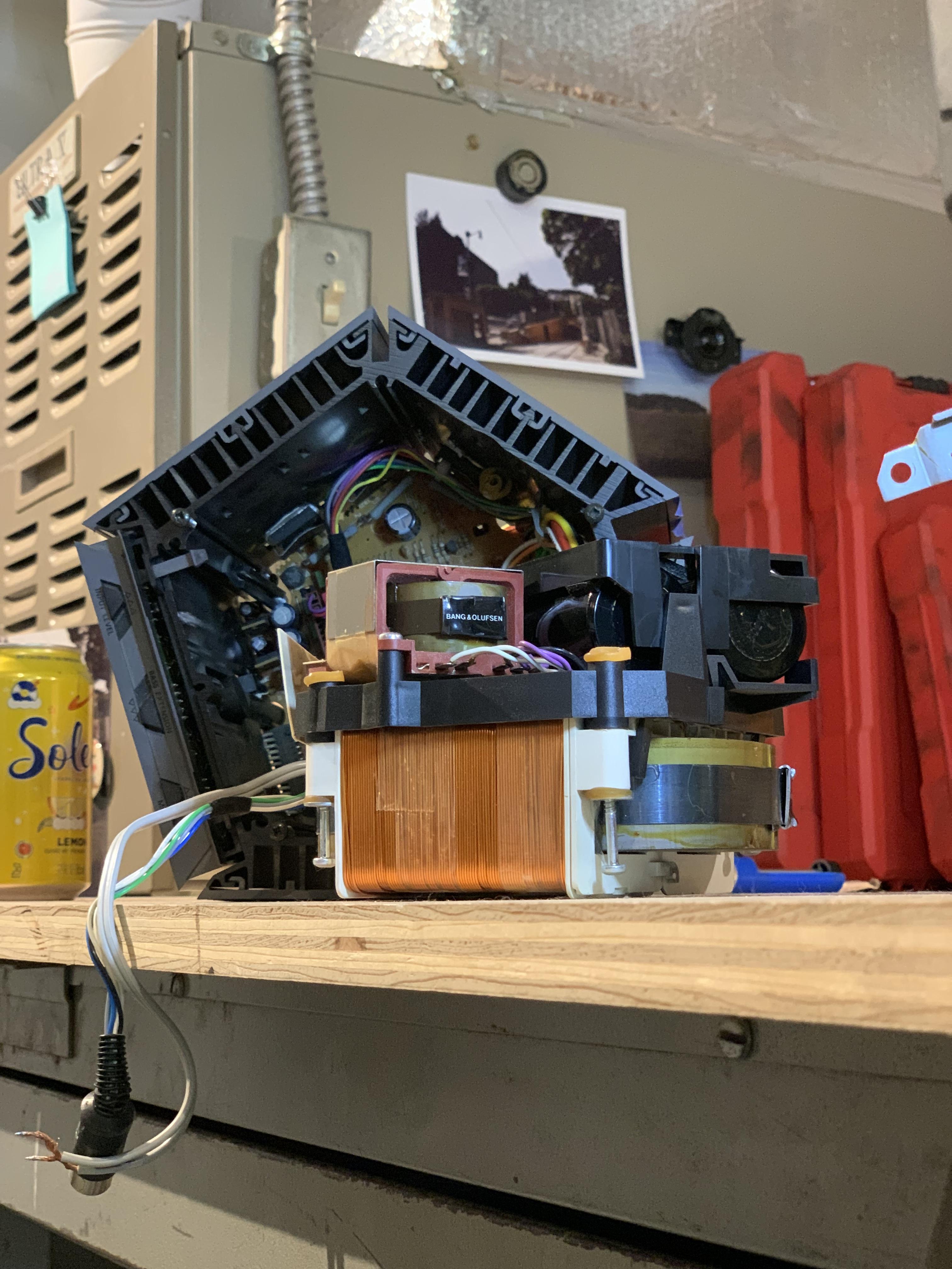
A closer look at what I mean. No slack in the wires and they are nearly tied in knots through those solder lugs. I tried to surgically remove the wiring exactly as it was by de-soldering with a pump and painstakingly maneuvering the wires out but in the end it wasn’t worth it.
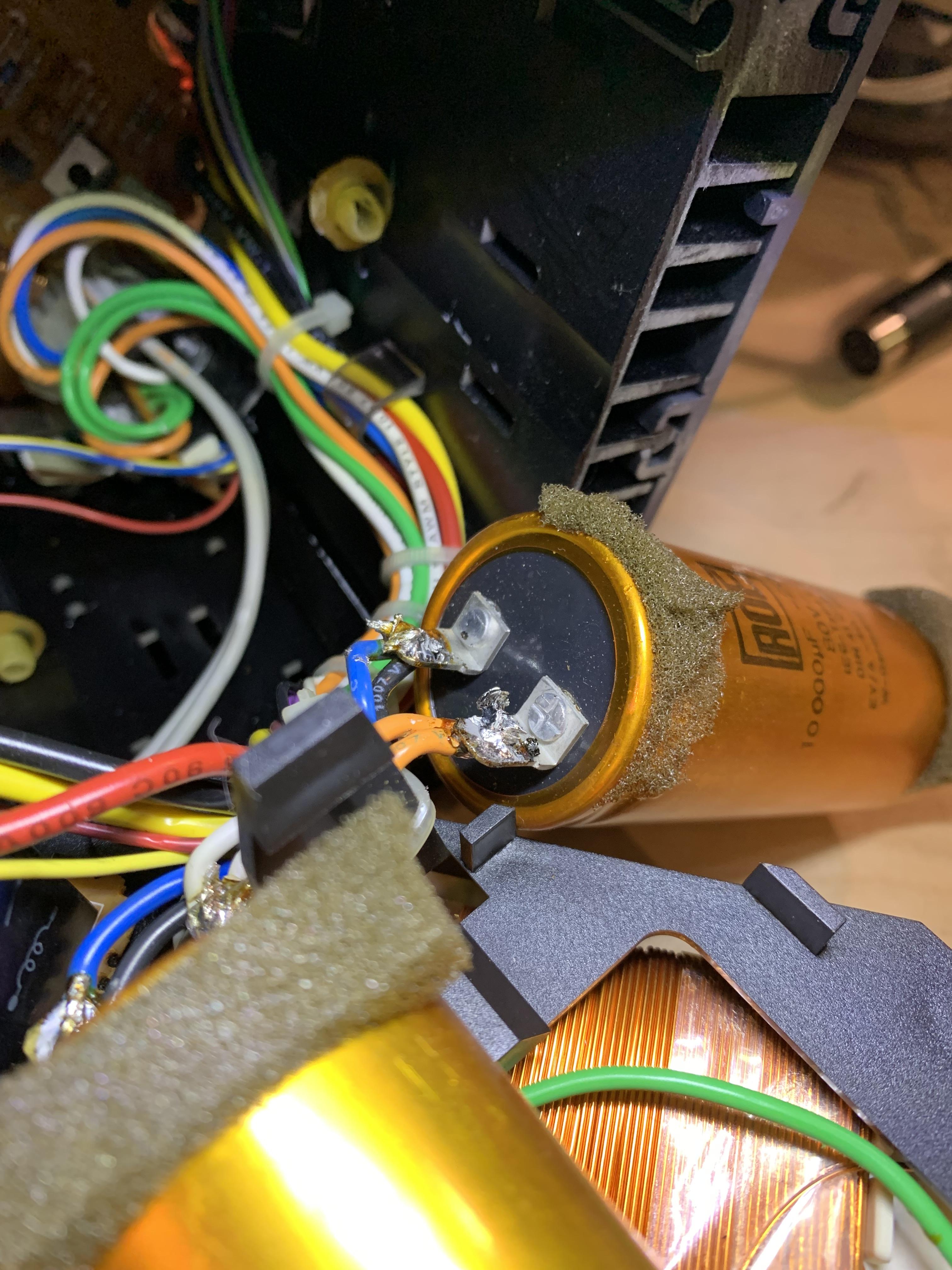
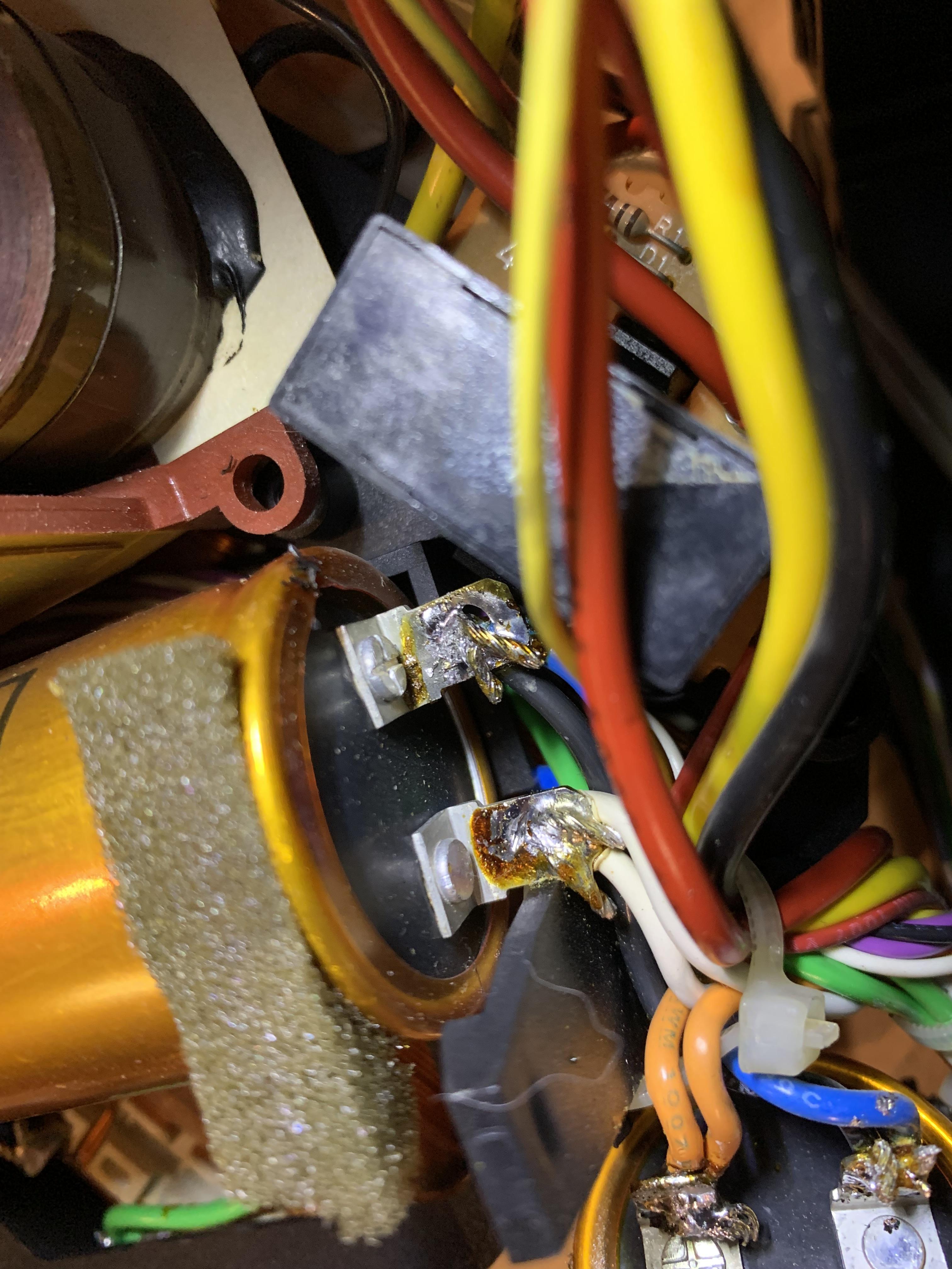
In order to get the new caps to fit in the black plastic holder, I needed to add some wire so I soldered on some extensions ultimately.
First thing was to get the main power caps swapped out. Seemed easy enough! Turned out, like many things in this amp, to be a highly-tedious process due to the cramped nature of this beast. The cable routings are exact. No real wiggle room to get things in and out and the lack of extra wiring harness made it extremely tough to get the connections made without burning things nearby with the soldering iron.
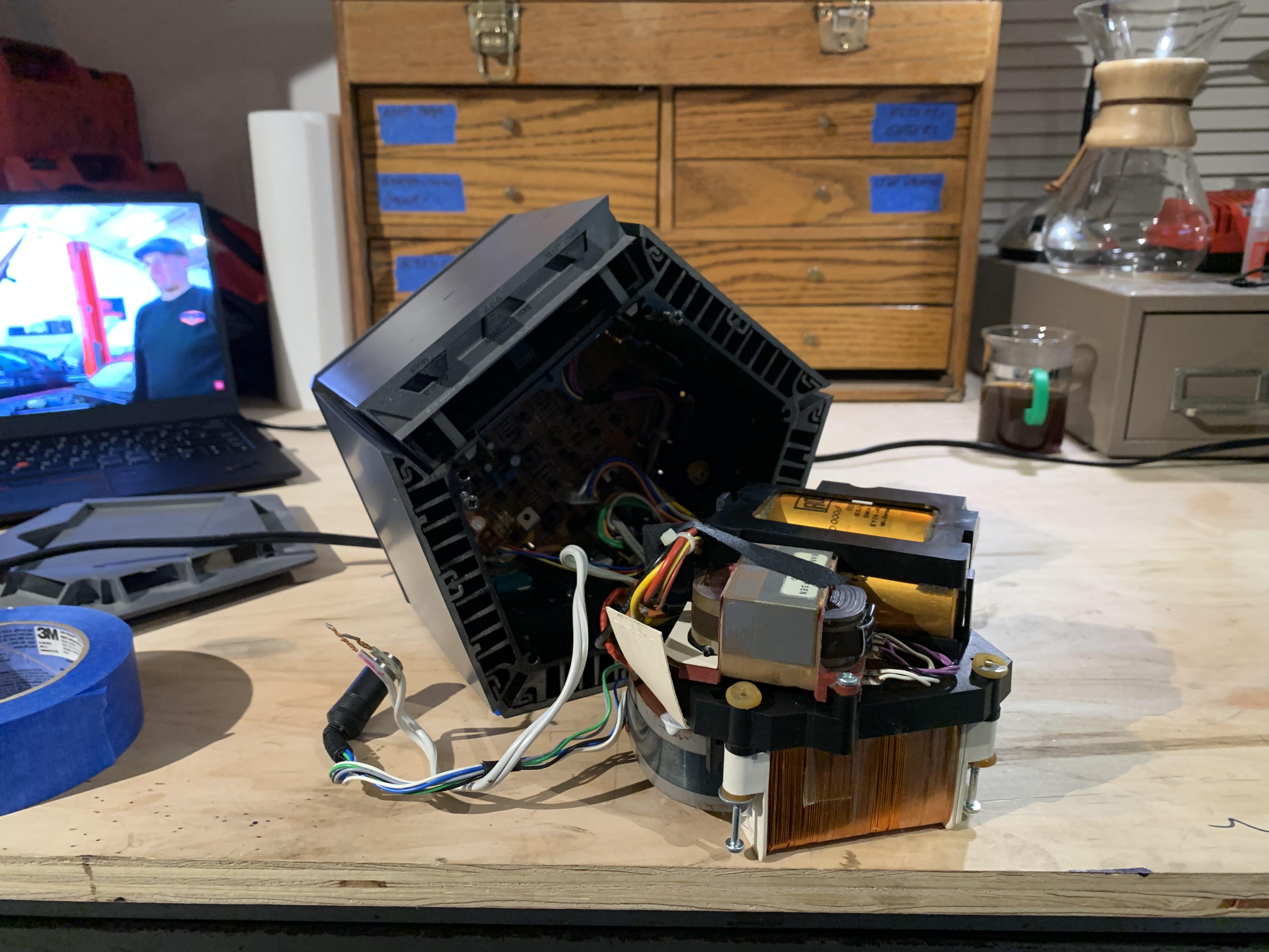
In the background I was watching the AutoAlex series on his new Jag XJR-6. Highly recommended! Judging by the coffee hardware in the background this was clearly an AM session!
Loving this thread
Glad you like it! Had to take a lunch break, now back at it.
See what I mean?? This is amazing. Yes, those power supplies actually fit in there!
This level of disassembly is unfortunately necessary, the power caps (and all other caps to be honest) live in the core of this beast.
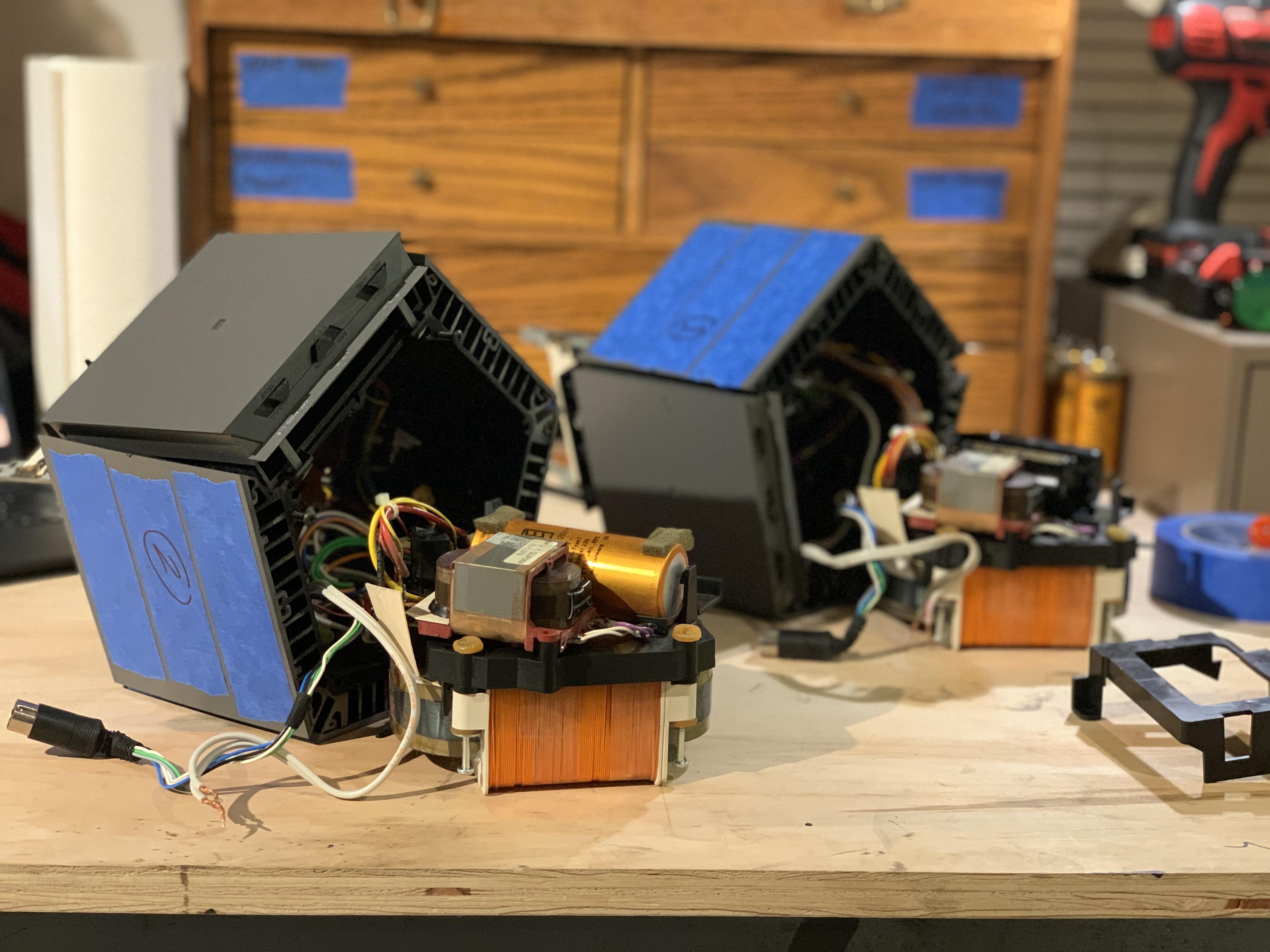
Now time for the amplifiers. Man do these things need a lot of disassembly before you can really get to the matter at hand. Not to mention the actual task of working inside a pentagonal heatsink. However that was also something to marvel at. The engineer in me is very impressed that this amp even exists. The heat sink is clearly just big enough to hold the transformer and there seemingly isn’t a single right angle among any two components. Packaging this thing mist have been hell. If anyone from the original Penta project team is reading this, I’d love to know more about this. Did you guys/gals use CAD to develop this package?! Even if you did, I’m impressed.
Never mind the poor photo, this was mostly just to keep track of cable routing.
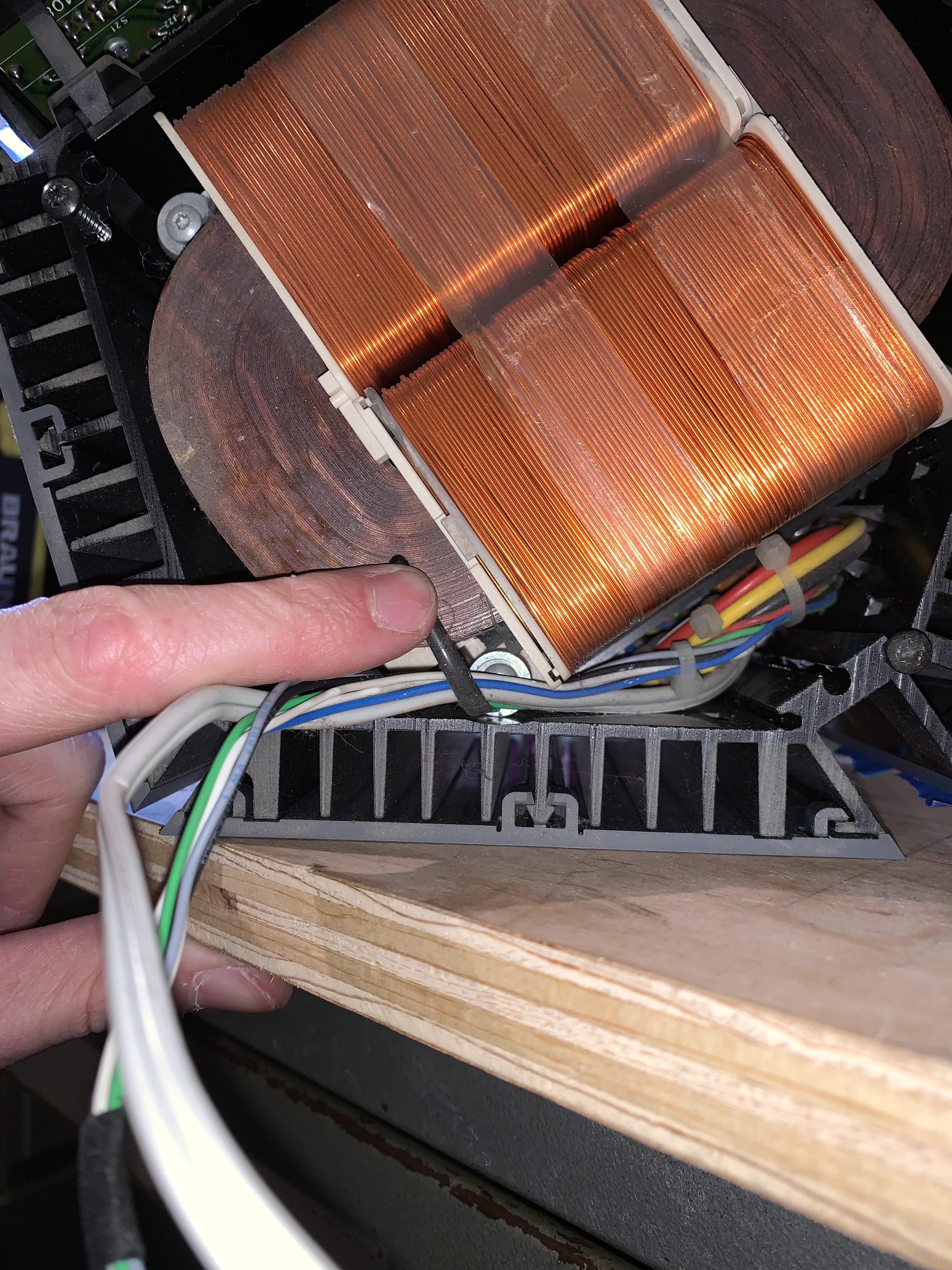
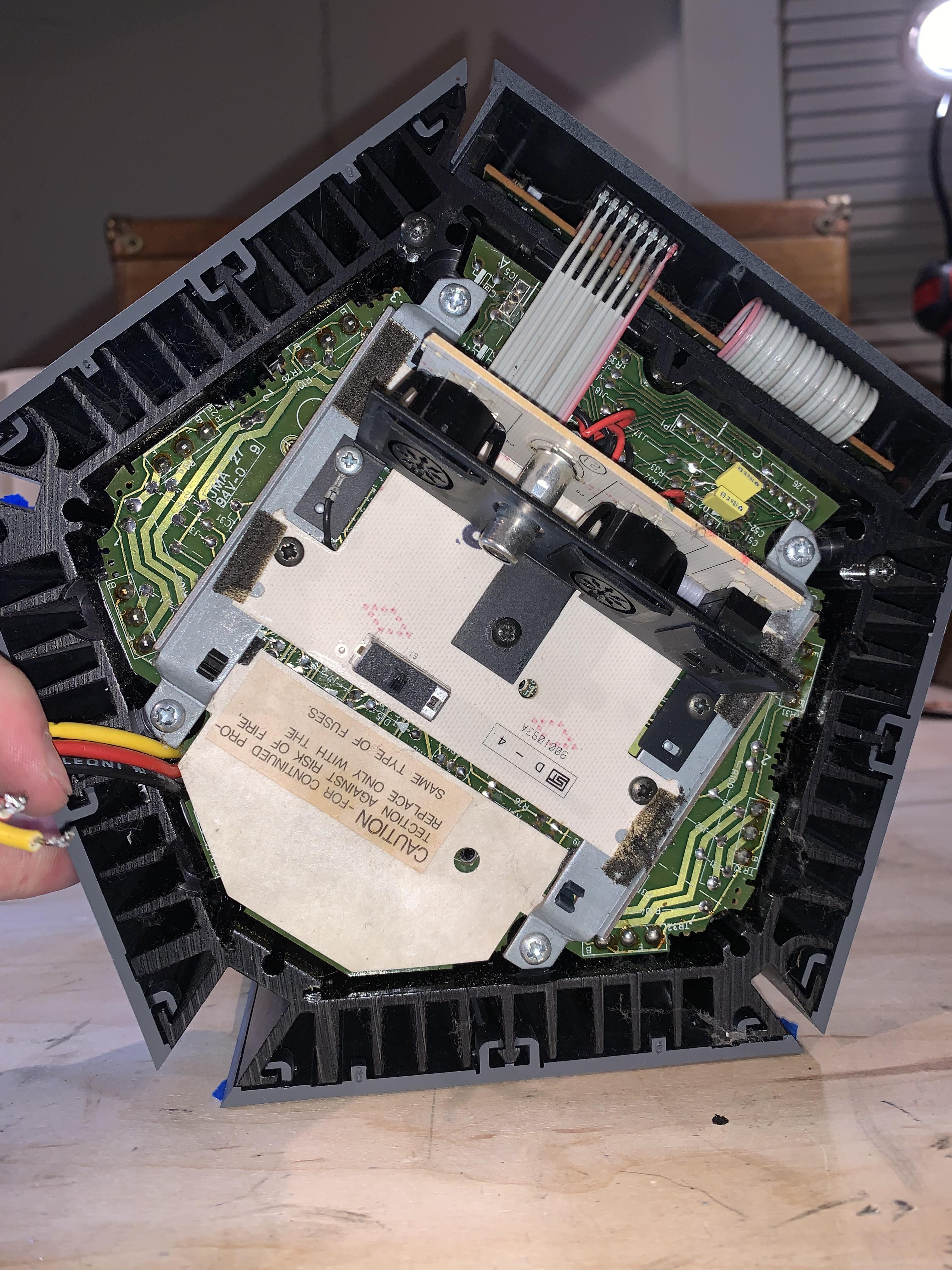
Now that the gray trim pieces and power cord are off, its time to pull out those power supplies.
- AuthorPosts

