alexsalles
Forum Replies Created
- AuthorPosts
-
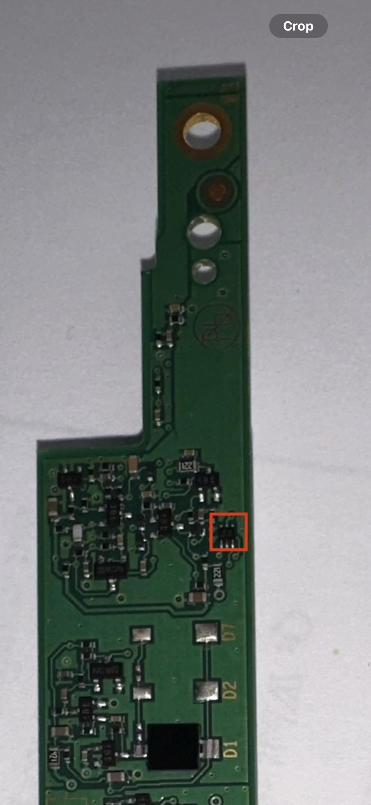
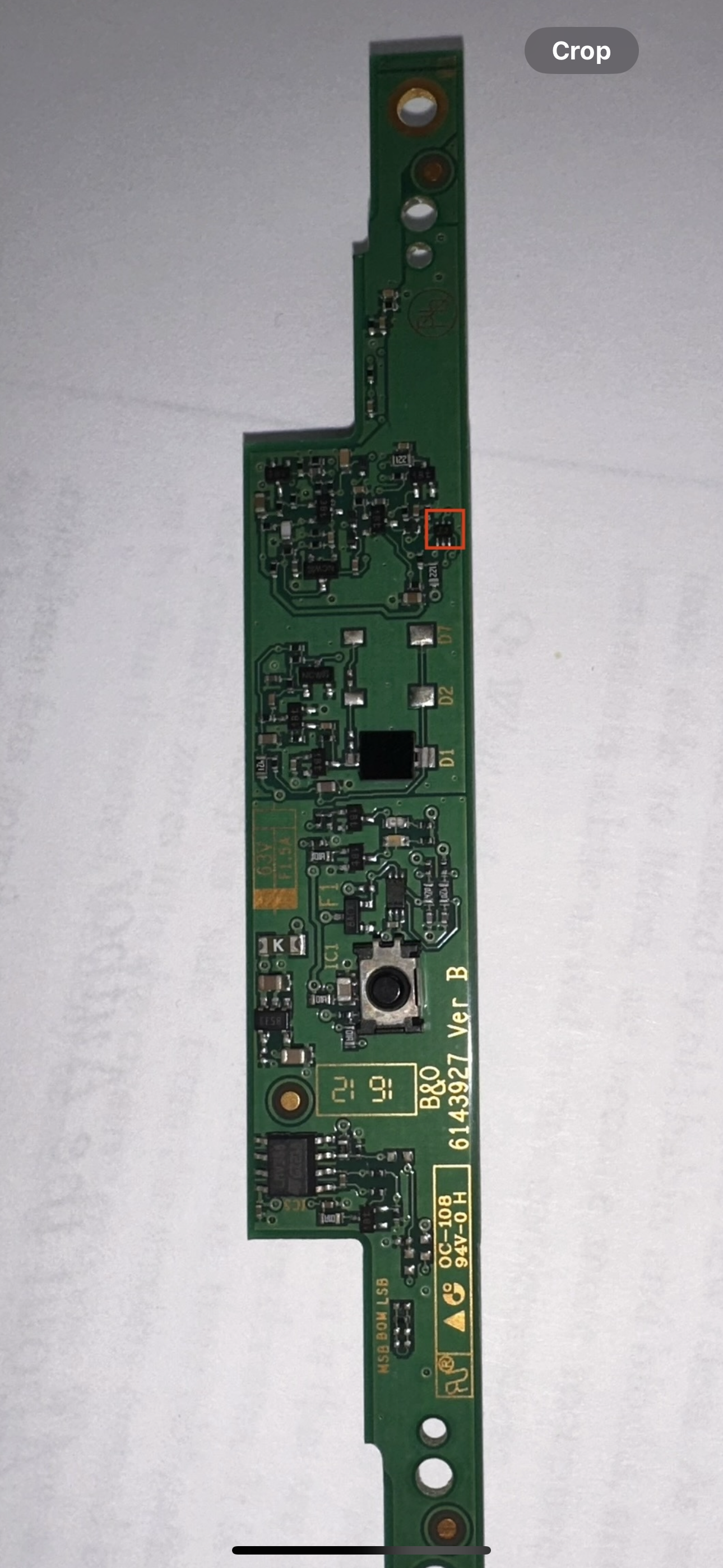 I think it was this part I highlighted in red square. I have to take the black cover off to see for sure if it is only this component.
Fair, I’ll buy it and see how it goes. It’s the easier way to find out the origin of the issue. I’ll let know you the outcome after I install the new PCB58.
Thank you very much for your thorough help and advice! I would be lost without you.
The pin position was correct but then I tried with the mains plugged in and when I touched the pin with the multimeter something on the awareness board blew up. It still shows 5volts but now nothing changes as i screwed it up.
I dont l know for sure if I accidentally touched between the pins and it cause that but now I know for sure that awareness board is gone hahaha even smoke came from it. I found a board on ebay now 110euros with shipping.
at this point I dont even know if it’s worth fixing this tv. Was the problem something else on the video engine and now that I made that part blow up would it affect the video engine in case it was okay and the problem was really the awareness one?
So I measured it with the multimeter on DC on a screws on the board and on metal parts for ground on that pin number 4 on the P101. and the numbers are most of the time on close to zero it doesn’t seem to react to the remote at all.
just with the multimeter if the remote awareness was working by the time i touch the pin 4 it should be giving 5V and then go down to approx. 3.8v, correct when the colored buttons on the remote are pressed, right? not changing any value on the screen by touching or pushing the buttons on the remote means this awareness board is dead and probably the culprit?
The tv doesn’t need to be on, right? i didn’t turn it on for that test.
Thanks again Madskp
Would this issue be on the T-CON board or video engine board ?( even tho it is functioning without image) and the remote not working can be a related or a side effect from the video engine as the IR sensor is attached to it?
Not really sure, but the fact that the IR board connects to the video engine makes it possible that it can be a fault on another board then the IR.
1- By another board you mean within the video engine board or another one?
Also on the room awareness module, there a dark spot on the side of a white thing, is that an indicator that it was blown or something?
It could be something. I can’t locate it on you pictures. Could you make a close up photo of that component?
This is the back part I missed attaching it. Is that component that has “H CM . &” a capacitor?
Thanks @Madakp for the help.
So I connected the ethernet cable to it and I was able to turn it on via the b&o app, but there is no picture, I managed to play the radio and it works fine but all I see is black screen. And it still doesn’t respond to the remote.
Would this issue be on the T-CON board or video engine board ?( even tho it is functioning without image) and the remote not working can be a related or a side effect from the video engine as the IR sensor is attached to it?
I took some close ups of the boards. the back light one seems like there is some leaking around some parts (brown one and the big black piece) I noticed it today.
I havent checked voltages yet, I need to learn how to do that.
Also on the room awareness module, there a dark spot on the side of a white thing, is that an indicator that it was blown or something?
I had that component replaced and it still doesn’t turn on.
Ive been studying the service manual and it could be that the “IR Receiver & Room Awareness” ( 58Module 8007282 PCB58) need to be replaced. My light turns green for a while which they say on the manual the TV is ready to be used.
Like it doesn’t react to my remote at all and I tried other B&O remotes I have working on other tvs and it doesn’t turn on. I’ve been looking for that module part online and so far no luck. I wonder if the cable that connects to it might be damaged (photo) anyone know what kind/name this cable is?
I still have to take the video engine board out to see if there is corrosion, from the top it looks fine.
I found the capacitor on ebay, https://www.ebay.ie/itm/292412377560 just €8.
I will update you guys if that fixes it. Thanks for all the help!
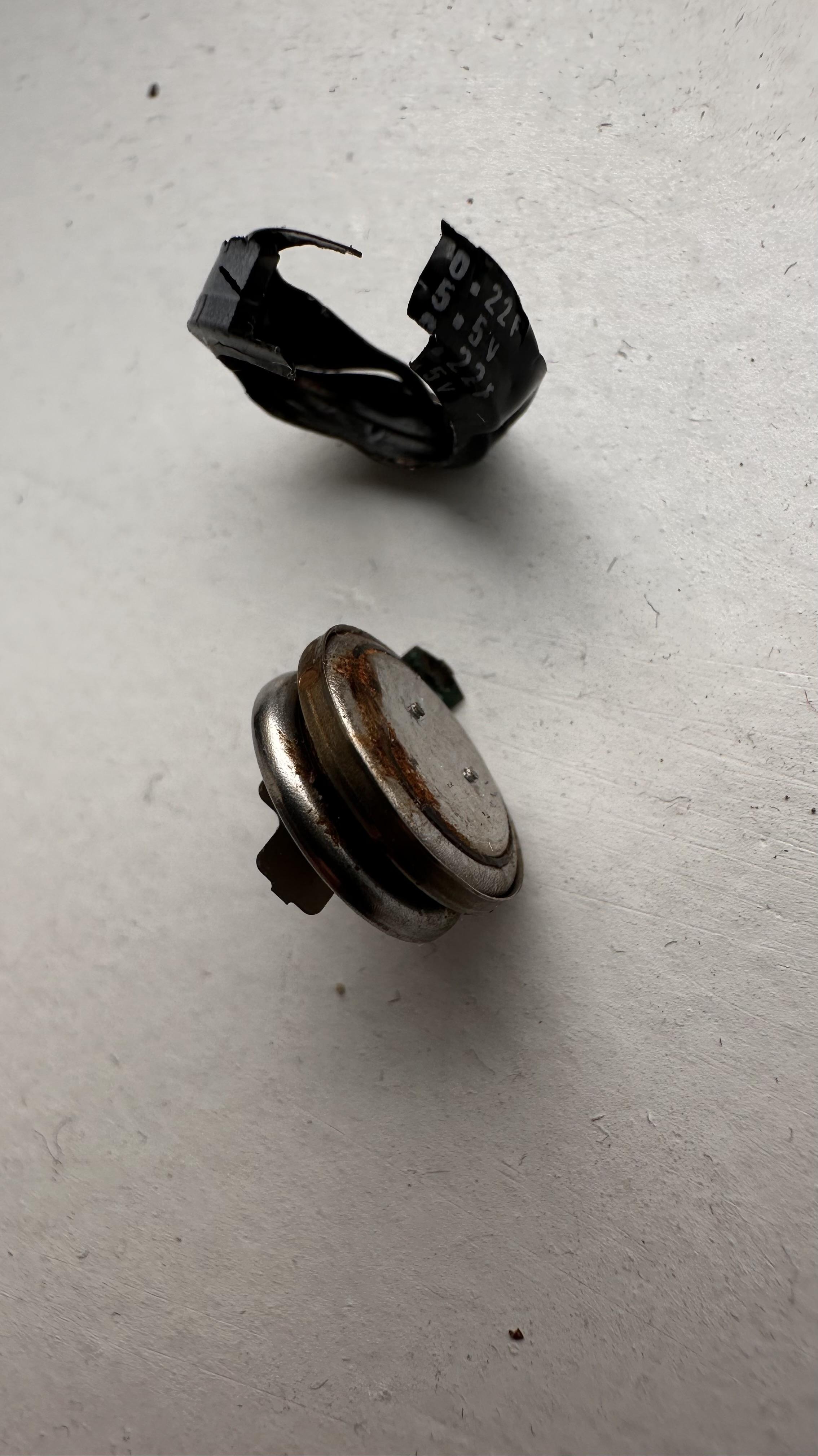
I took them apart they seem like batteries, I wonder which kind, any ideas?
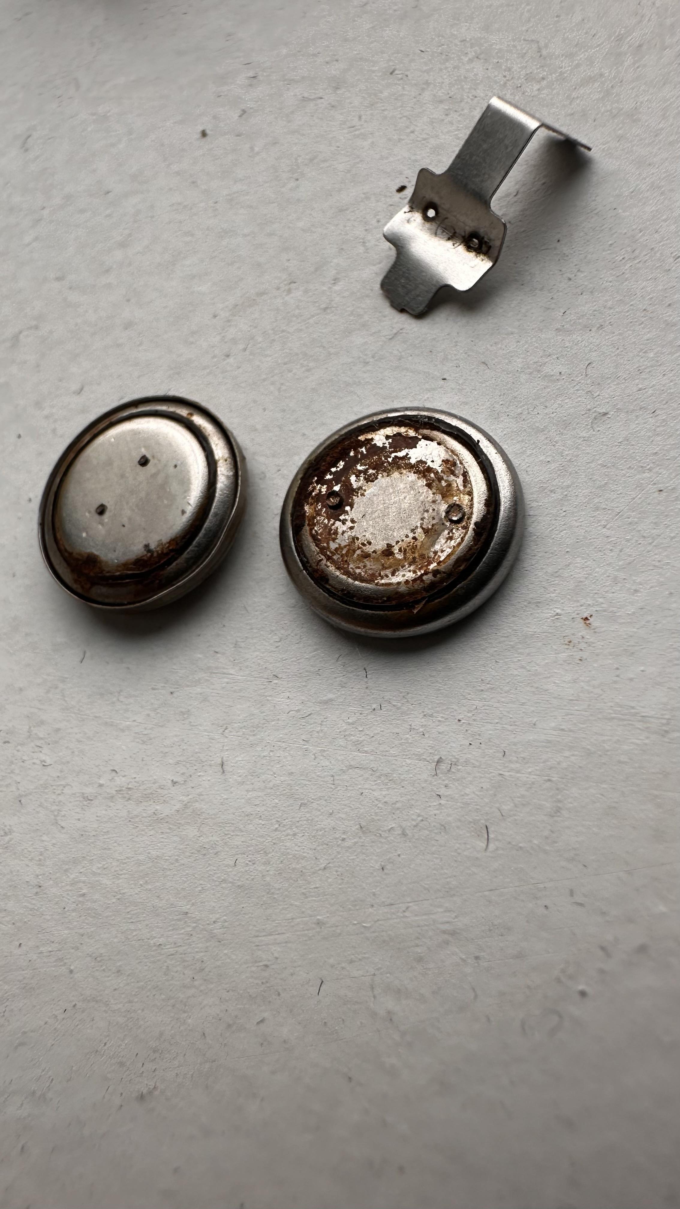
Im having the same issue with my V1. I noticed there are some voltage written on black thin plastic label around it. and suddenly that come apart and they look like two batteries.
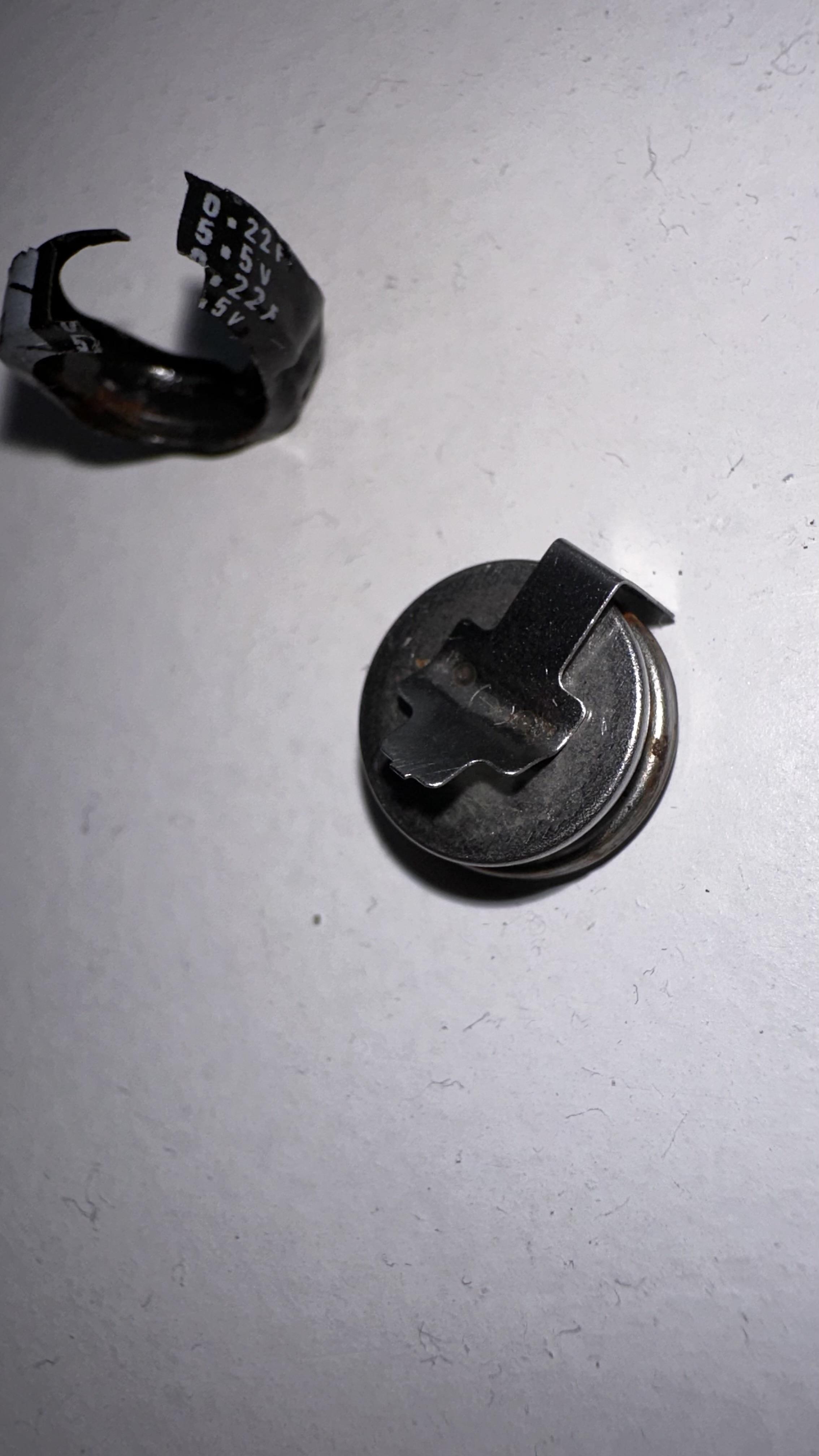
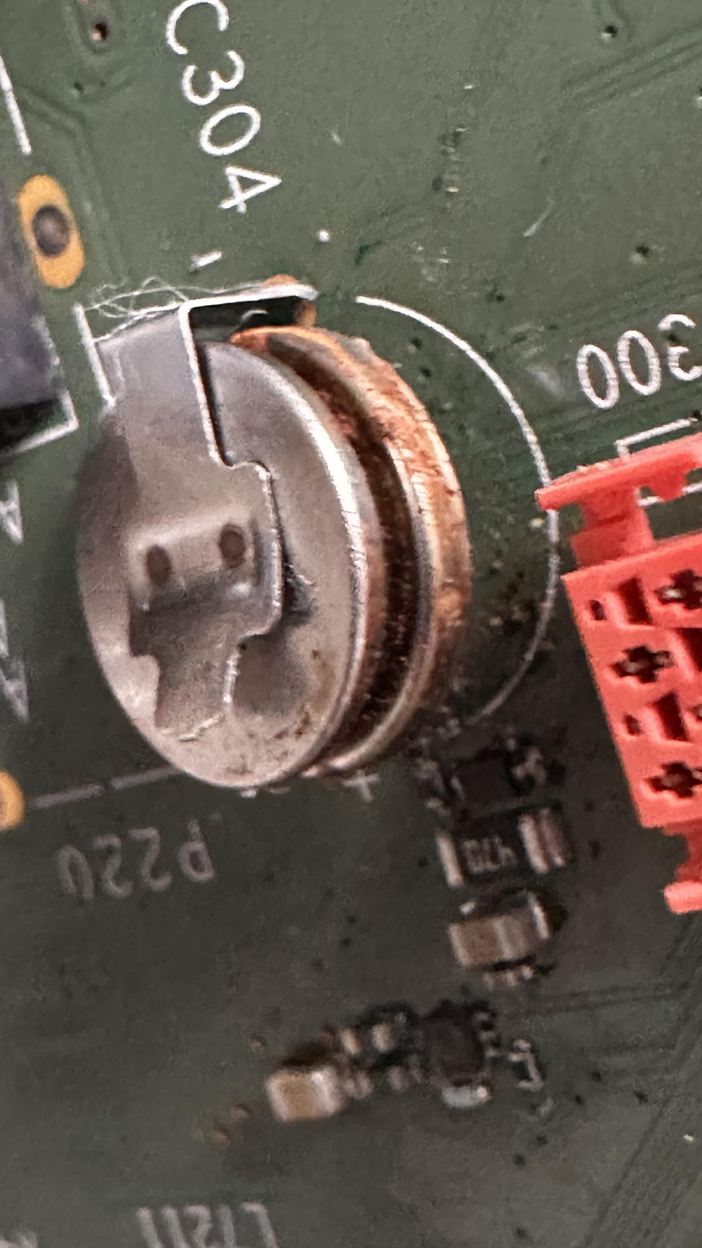
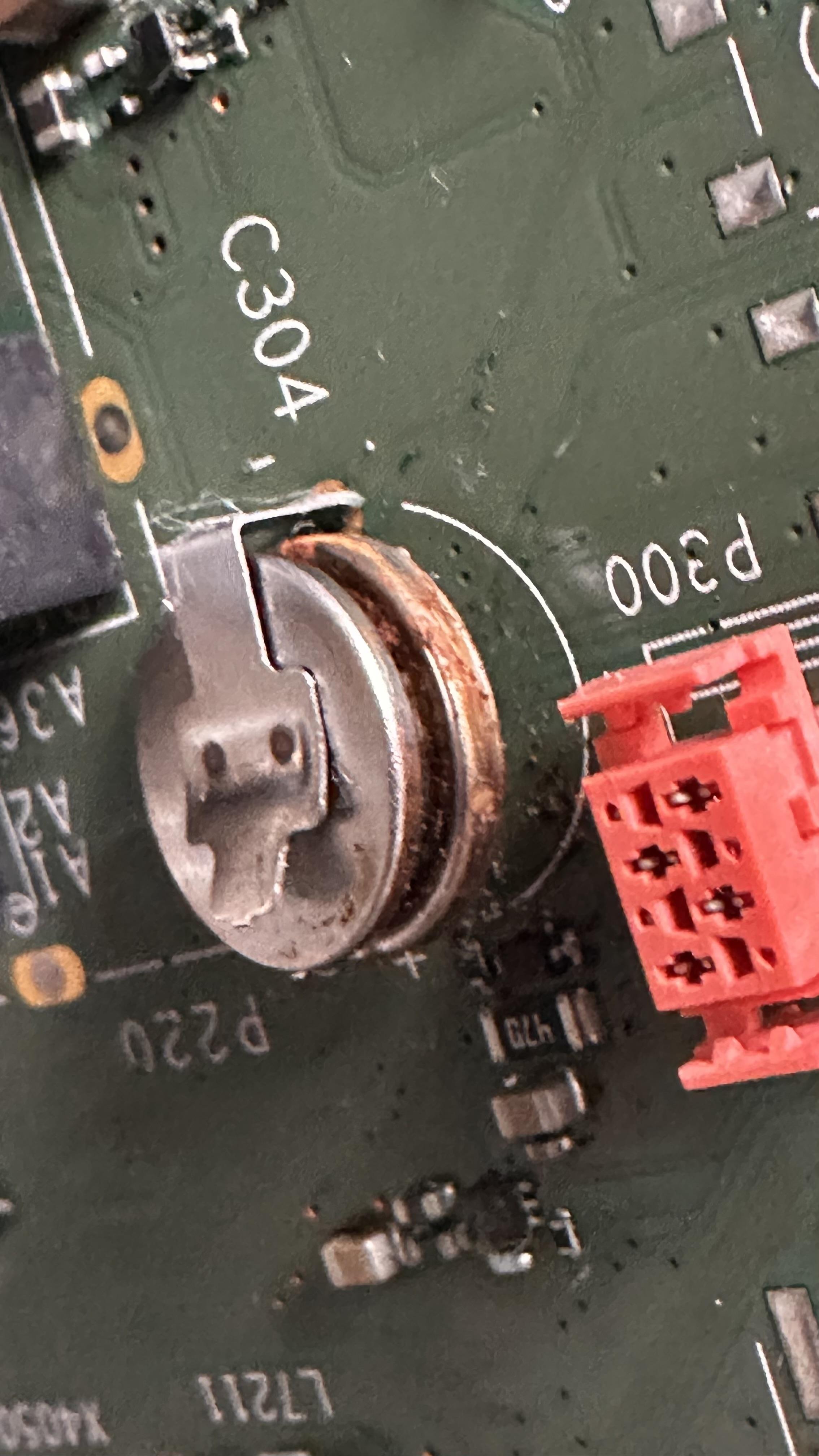
I tried to remove the soldering that was holding the clip and I ended up getting the whole clip off the board.
Anyone has an idea how to remove the clip from the battery and which kind of battery will fit here? they dont seem to have anything written on it apart from some voltage and amperage on the plastic label.
is it two batteries or the lower one is is the actual battery and the top part is a holder that got rusted on it and made them too stuck together?
I did mine, got the wood the way I wanted but the clamps I got 3D printed locally and I wasn’t aware 3D printer can vary printing quality so much. Mine did not clipped well and most didn’t clip on the clamp at all, I had to glue the slats. I was checking etsy and saw this guys that sells the clamps. so if anyone is not finding a way to get them on the link I shared.
********************************************************
LINK REMOVED – THIS IS PLAIN PIRACY: THAT GUY SELLS
MODELS THAT ARE AVAILABLE HERE FOR FREE
PRETENDING IT IS HIS DESIGN AND ALSO GIVE THE IKEA LIKE
USER GUIDE YOU CAN FIND ON PAGE 1 OF THIS TOPIC.DON’T BUY THIS CLAMPS AND DON’T PROMOTE PEOPLE
WHO ARE SELLING THEM, PLEASE !
********************************************************Thanks to member sydk for bringing this to my attention.
- AuthorPosts
