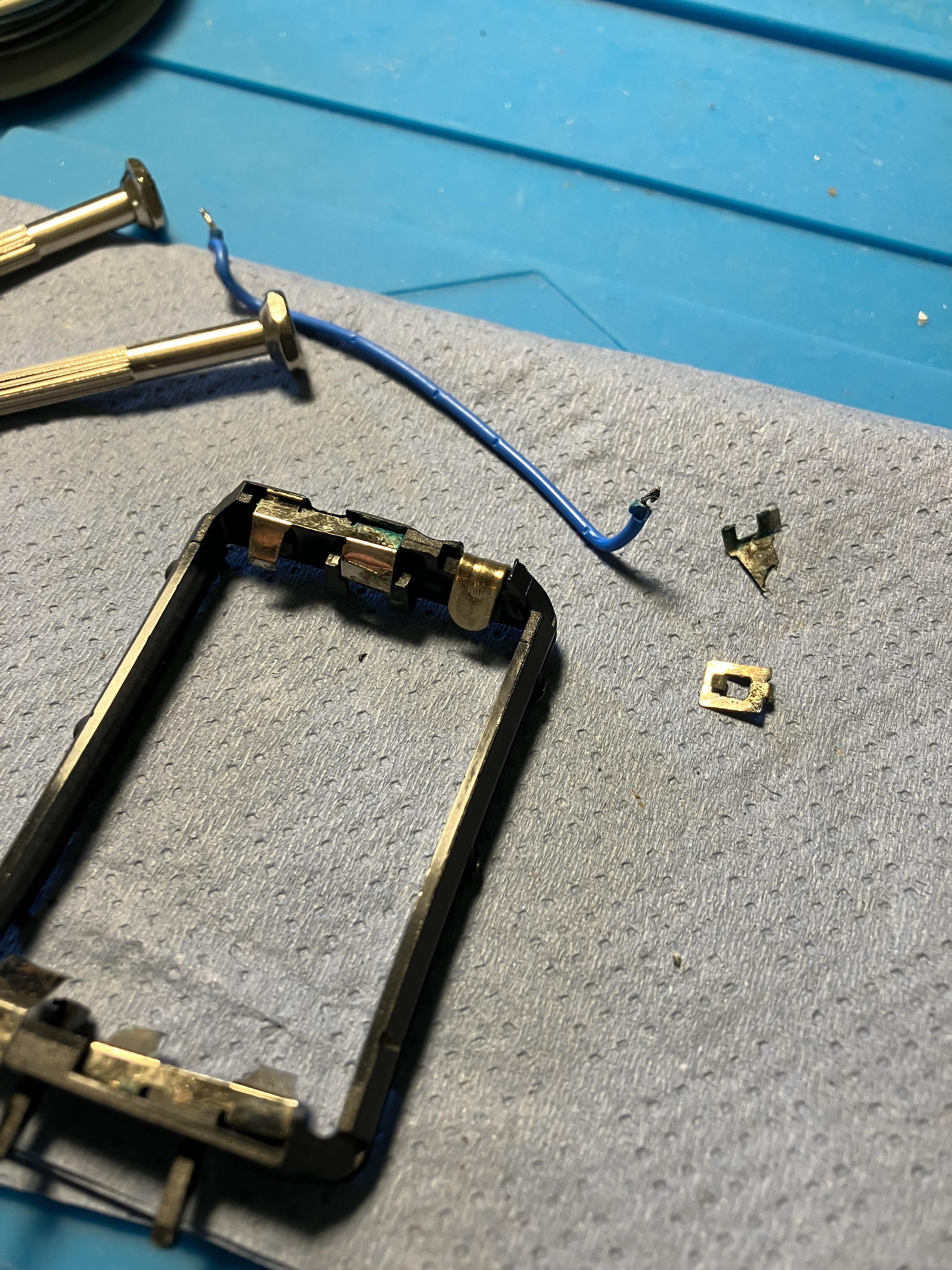
What are you working on now?
- This topic has 107 replies, 27 voices, and was last updated 1 year, 1 month ago by
Guy.
- AuthorPosts
- June 17, 2023 at 7:54 am #21378
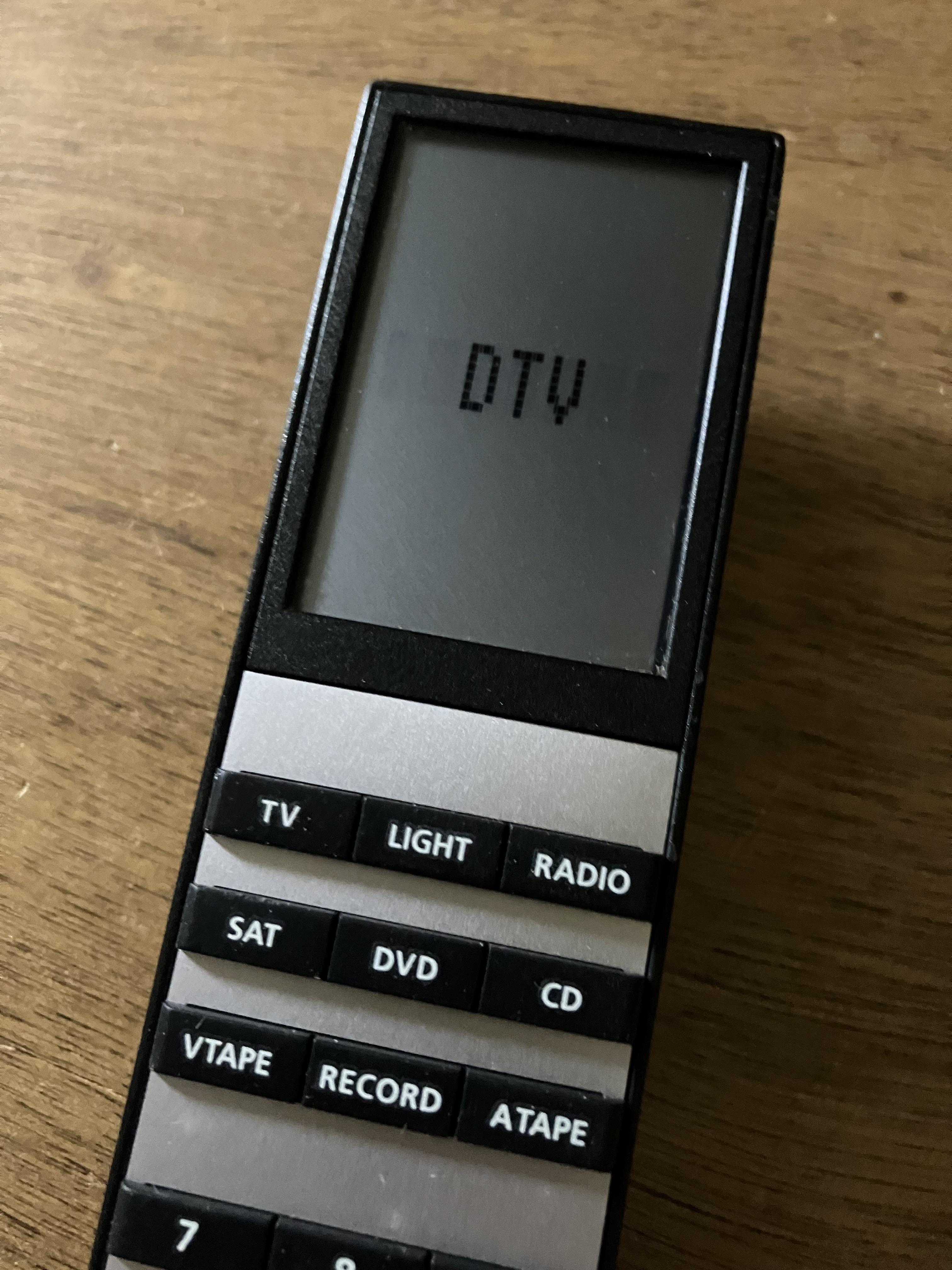
Then cleaned up yet another Beo4 remote and must have been on auto-pilot because I didn’t spot the obvious mistake until re-assembled!
 June 17, 2023 at 8:37 am #21379June 17, 2023 at 8:41 am #21380June 17, 2023 at 10:34 am #21381
that is perfect as a IR command converter then
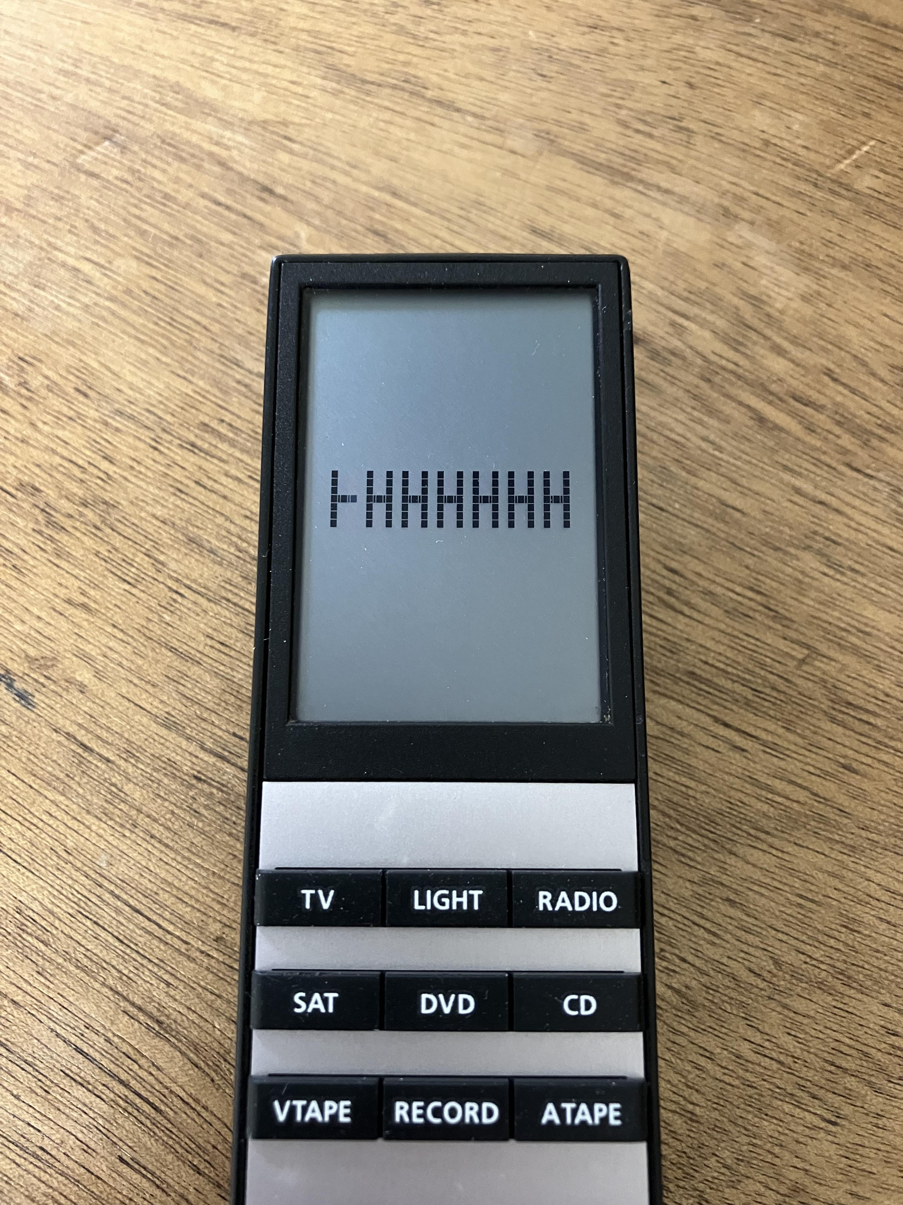
Ha ha! My OCD won’t let me leave it like that! I replaced the keyboard because a previous owner had picked away at the volume button and that was annoying me. It’s actually a tatty one that I leave on my desk to check my answers to Forum Beo4 questions. It also has a missing pixel line on the screen but it’s over to the left hence rarely appears.
 June 17, 2023 at 2:13 pm #21384
We got one of these video terminals at home when I was a kid, and I remember wondering what the Print button was for. Now I may even wonder more that it it equal to the PC command. What equipement was it for?
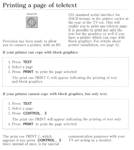
According to this thread:https://archivedforum.beoworld.co.uk/forums/p/38215/317414.aspx … it was supplied with the with the LX2800 and 2500 TVs amongst others. And the PRINT button may have been for printing out Teletext, although B&O never supplied a printer.
Ok that makes kind of sense as teletext was kind of the Internet of the 80’s, even though I’m not sure how such a printer would connect to a Beovision. Might have been preparation for future use though.
Back on the subject of the Video Terminal, I just found more about the PRINT button in the LX2800 manual:
I was actually also searching for the purpose of the ‘1 – 2’ button between ‘picture’ and ‘sound’. It is mentioned in the same manual, and was used for a few purposes:
- Switching between stereo and mono.
- Enhancing the stereo sound image.
- Switching between languages, if available.
In the back of the LX2800 manual there is also a quite complicated two-page table explaining use of the AUX and CONTROL buttons in conjunction with the ‘1 – 2’ button.
The manual also has further details of printer installation.
September 17, 2023 at 6:35 pm #24154One of the simpler projects: Updating the Beogram audio cable.
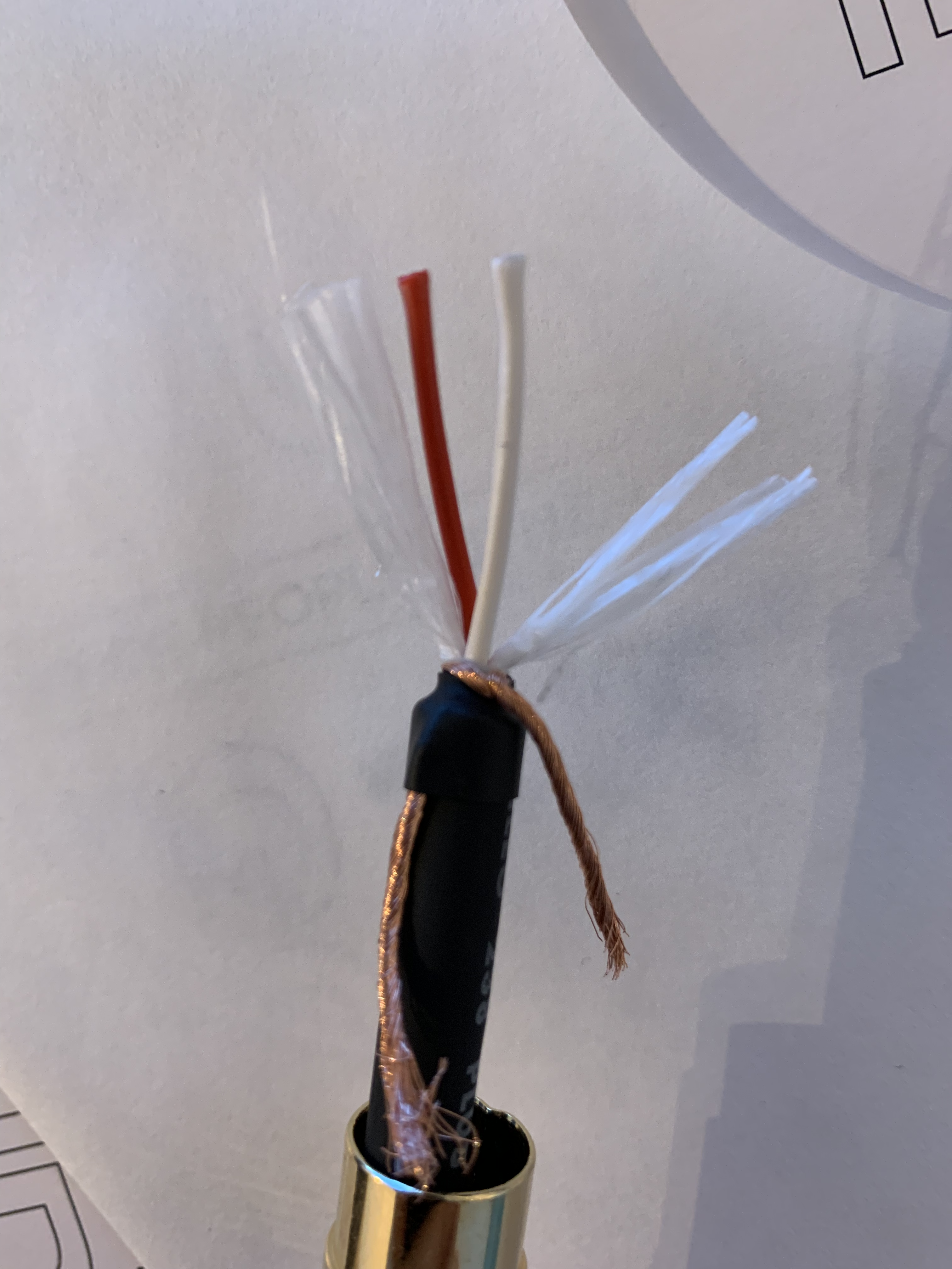
The audio cable on my Beogram 4000 had been shortened and, after checking the pinout, had actually been done wrong as the both shielding were connected to the same pin.

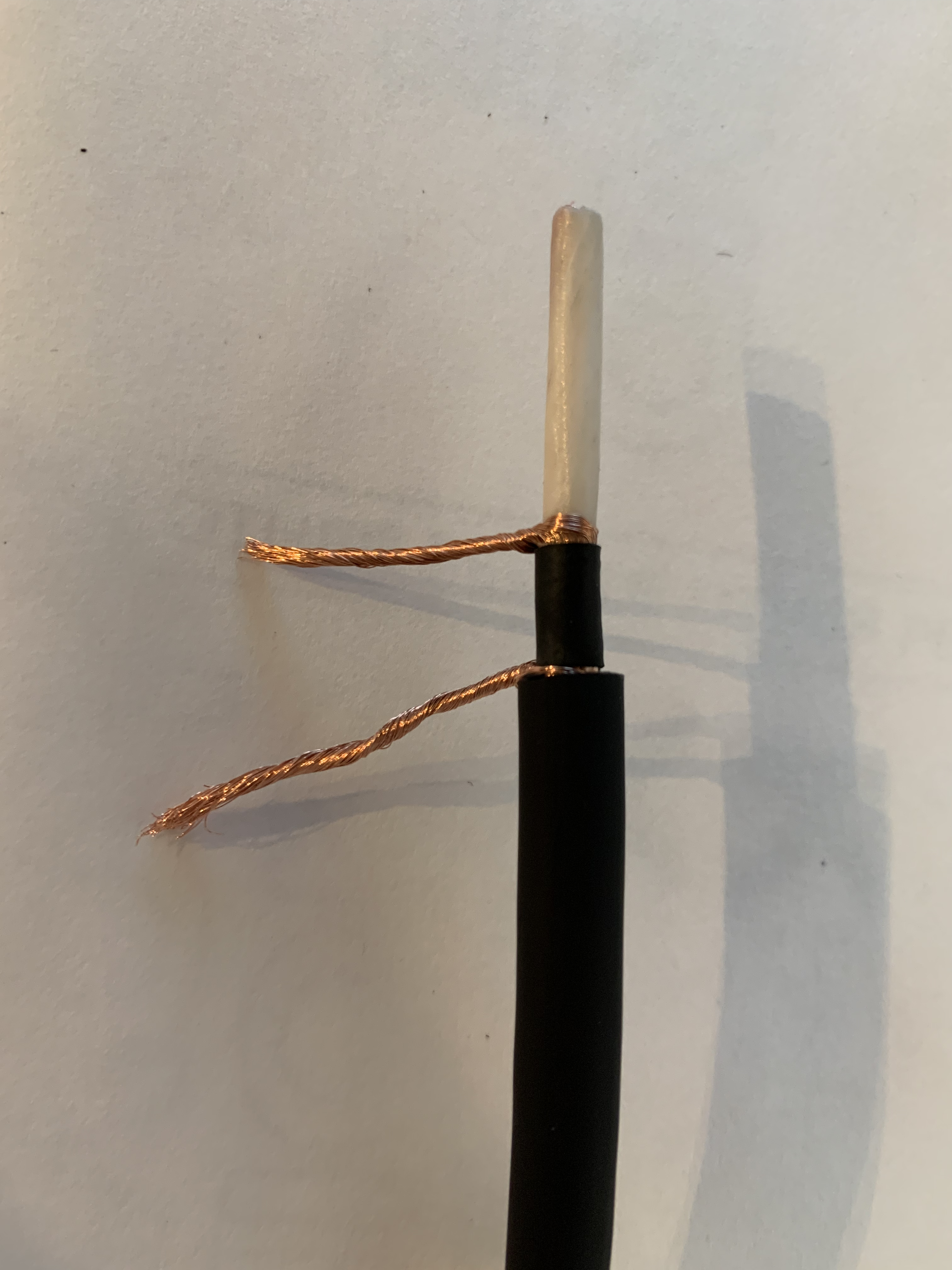
I bought Sommer Cable Galileo 238 Plus BK (2 meters) and a new DIN plug from Ryan (only gold was in stock, but I will not see it anyway).
Stripping the wire:
Sorting out the shielding:
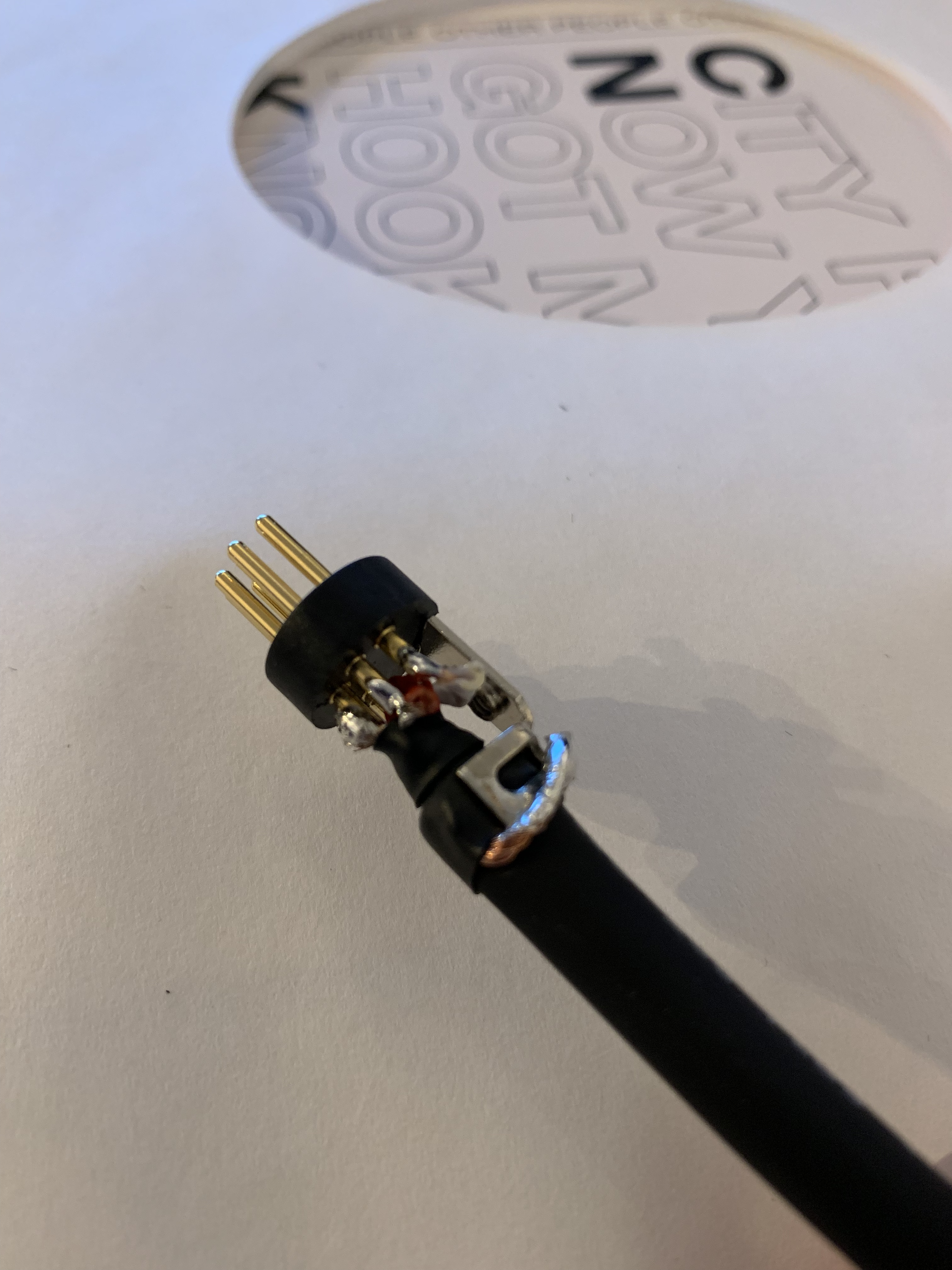
Soldering on the plug:
The result:
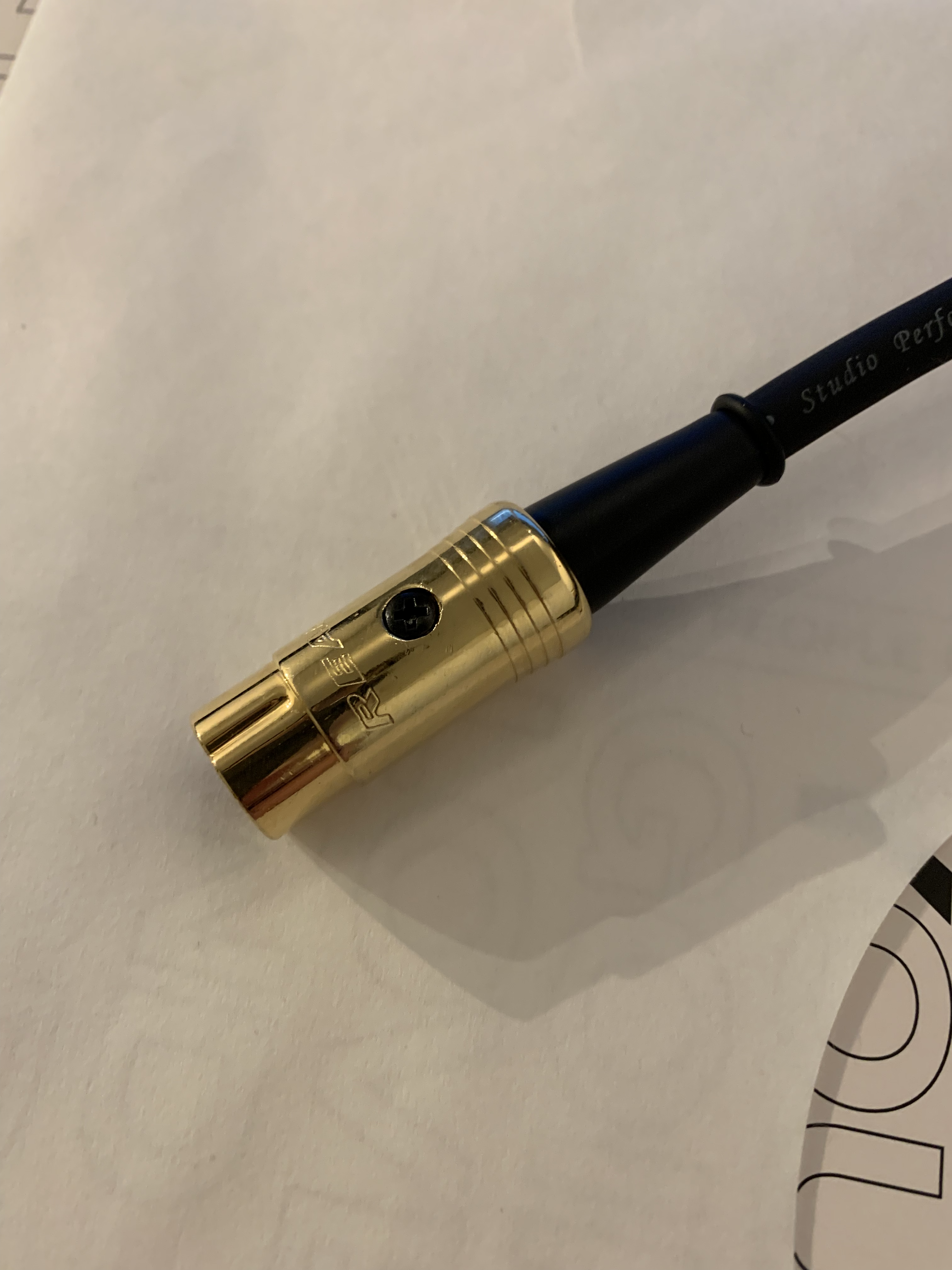
I also do the same to the power plugs as cable has usually yellowed and I feel its nicer it both cables match. Obviously this does not change anything with regards to audio quality, but it allows the extension of the cable and is a nice visual update.
September 17, 2023 at 6:55 pm #24155Nice job – but as I see it, there is no longer any shielding between the two signal leads.
There is quite an amount of amplification to whatever comes out of that cable, so even
the tiny amount of transfer caused by capacitive coupling between the two long parallel
leads close together could cause the channels to mix a little (loss of channel separation).
It’s marginal – that’s correct, but the old cable was in fact of better quality in this respect.The new cable would be better suited for balanced signals, really, – stage gear, microphones with long leads and the likes.
And you are absolutely right about the two grounds.
Martin
September 17, 2023 at 8:33 pm #24156i do agree that the original cable probably has better shielding between the two signal cables. The new cable has quite thick plastic shielding on the signal cables though, so I hope the transfer is neglectable.
Can you recommend a cable that is readily available that is better suited for the job?
I need to re-paint part of a Beogram 4000, do you have a recommendation when it comes to the black color used?as always thanks for your valuable input!
September 18, 2023 at 12:56 pm #24165It’s difficult to find cable of the same type as the original.
So far I have managed with what I could find in the dungeons from scrapped units and leftovers collected over decades from closed repairshops, but perhaps Steve can give us an idea?The original black color seems to vary a little. If this is because of age and sunlight or because the original production spanned several paint batches I cannot say.
A not-to-reflective but not exactly flat silk black either, should be close.Martin
September 25, 2023 at 1:30 am #24388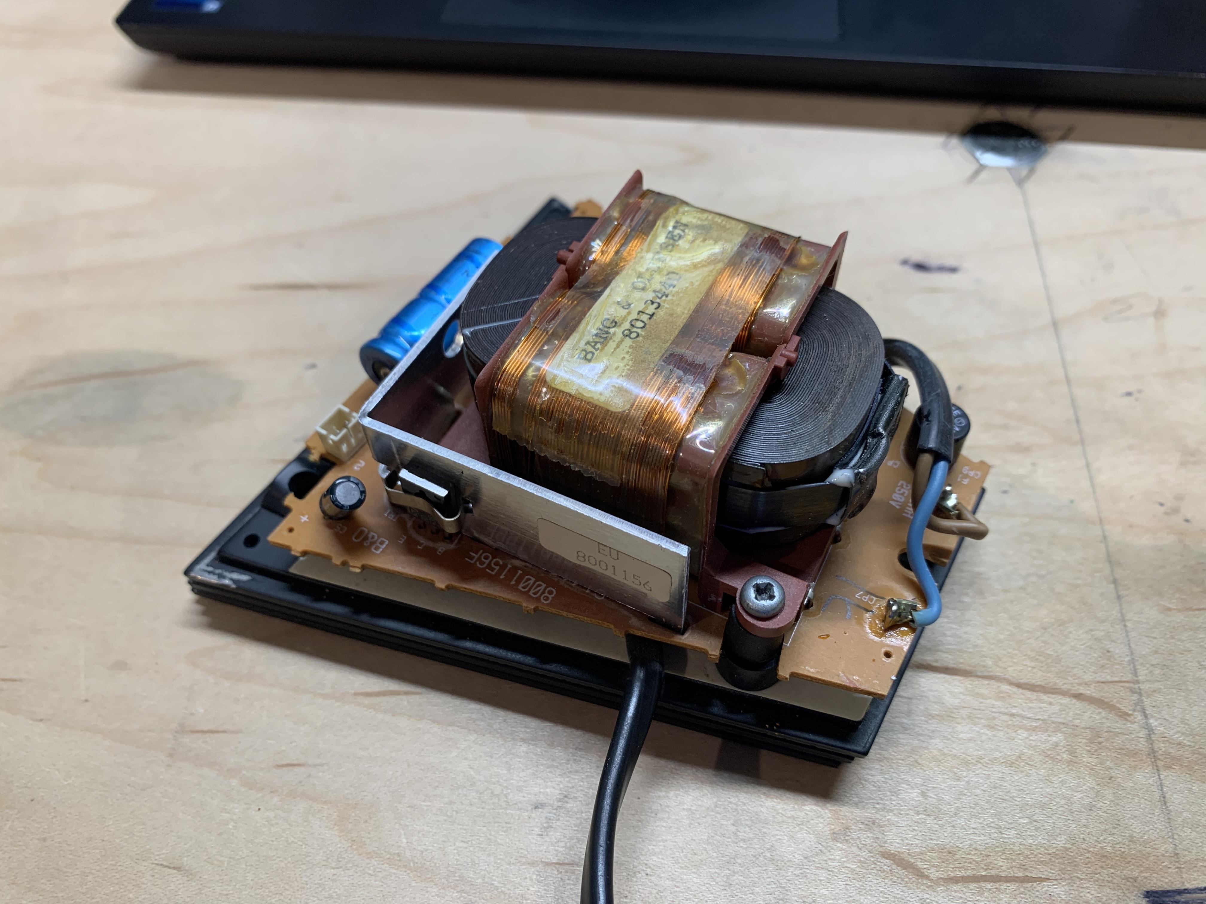
Hey everyone – I am slowly getting my Beo gear acquired in the UK/EU moved back to the US. The first to arrive was my BeoLink 7000 and charging base.
Is there a way to convert to 110VAC for use in USA? Service manual and a look inside the base themselves don’t offer an obvious method for doing so.
Thanks!
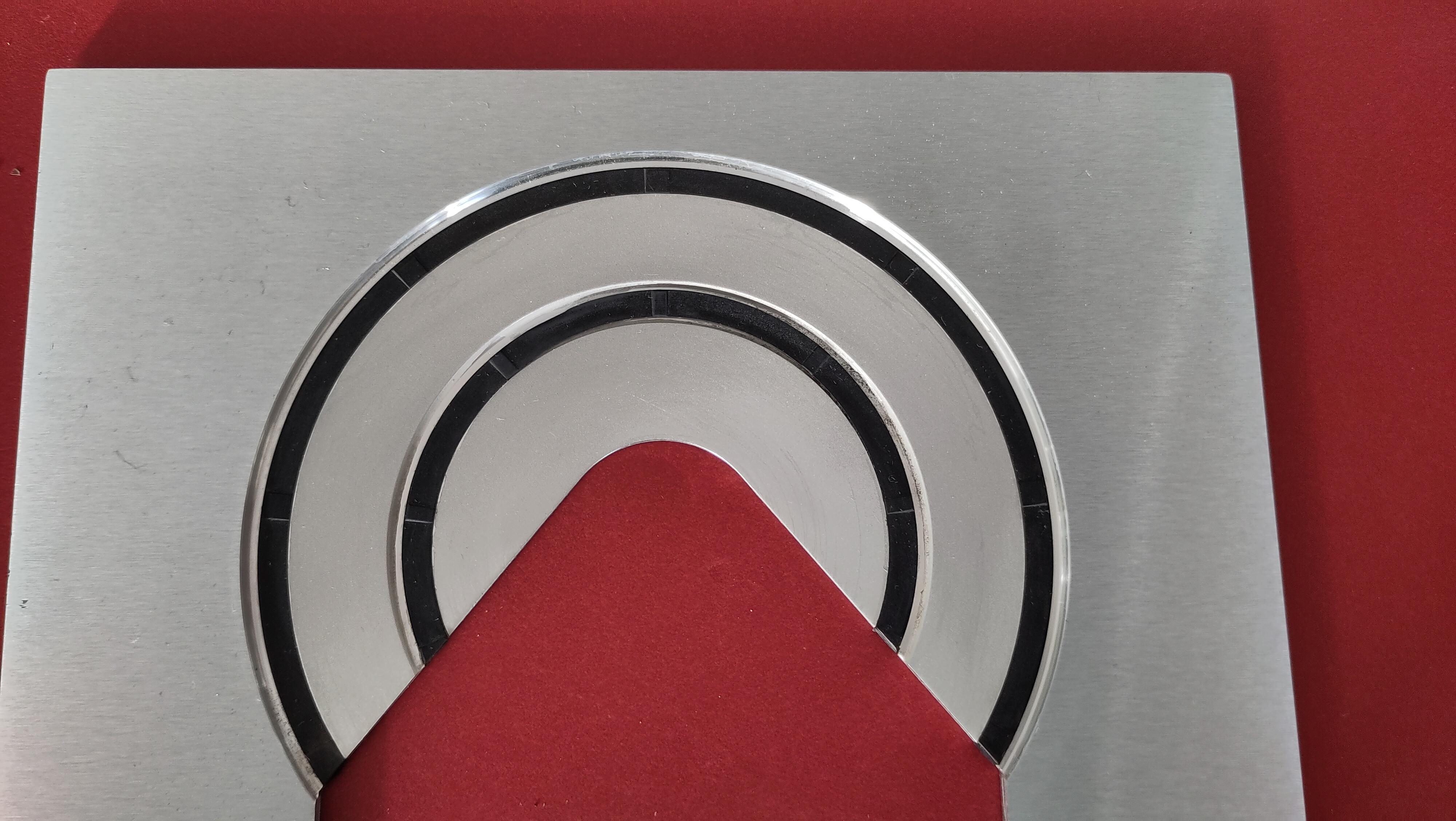
September 25, 2023 at 3:56 pm #24412I’m just restoring an Beogram CD 7000 which is optical in a very good condition.
Only the CD Tray had some ugly oxidation marks in the shiny middle area.
Since I also restore cars, I have access to a sandblasting cabin. Since the traces of oxidation cannot be polished away (it was turned shiny at the time), I sandblasted the area. I am quite satisfied with the result. It’s not original, but it almost looks like it 😉
Before: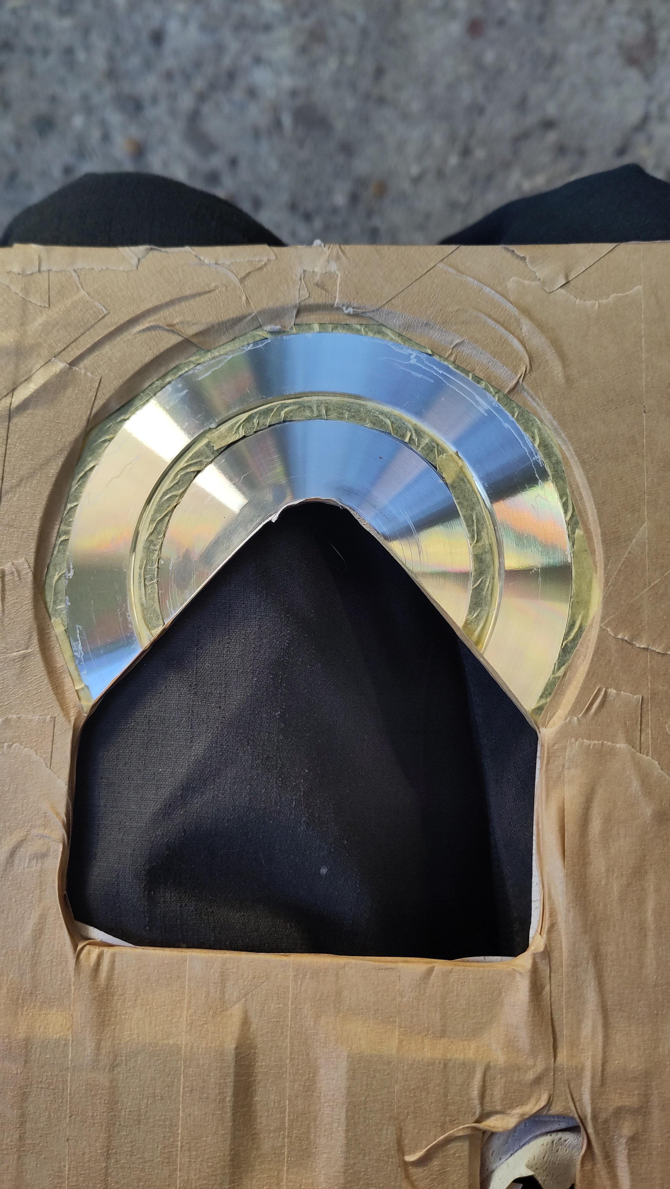
After:
 September 25, 2023 at 4:48 pm #24414
looks very good!
September 25, 2023 at 5:45 pm #24415looks very good!
Thank you very much!
October 2, 2023 at 10:30 am #24598Hello Evan:
Yes the charging base can be converted to run on 120. The primary of the transformer actually has two windings. For 24o, the windings are placed in series which is how yours is wired.
To make it run on 120, you will need to unsolder the primary lugs from the transformer. T Lift them off and fold them over onto the other side of the PCB so that it bypasses the traces which connect the windings in series. Then you can connect the windings in parallel.
You can also cut the traces on the PCB, but I prefer modifications that are non-destructive and can be reversed.
Derek
PS: I’m in SF as well!
October 7, 2023 at 6:26 pm #24711Hey Derek – Thanks for the info! No worries, there won’t be any traces cut here.
I’ll add another photo of the bottom, it seems like there is a trace that can be broken intentionally underneath (there is a pair of joined solder pads). This path runs under the transformer from what I remember, however I could be mistaken. I’m on vacation right now but will add a photo and try to identify the spot on the schematic when I return home.
Glad to read there are other BeoWorld members in SF!
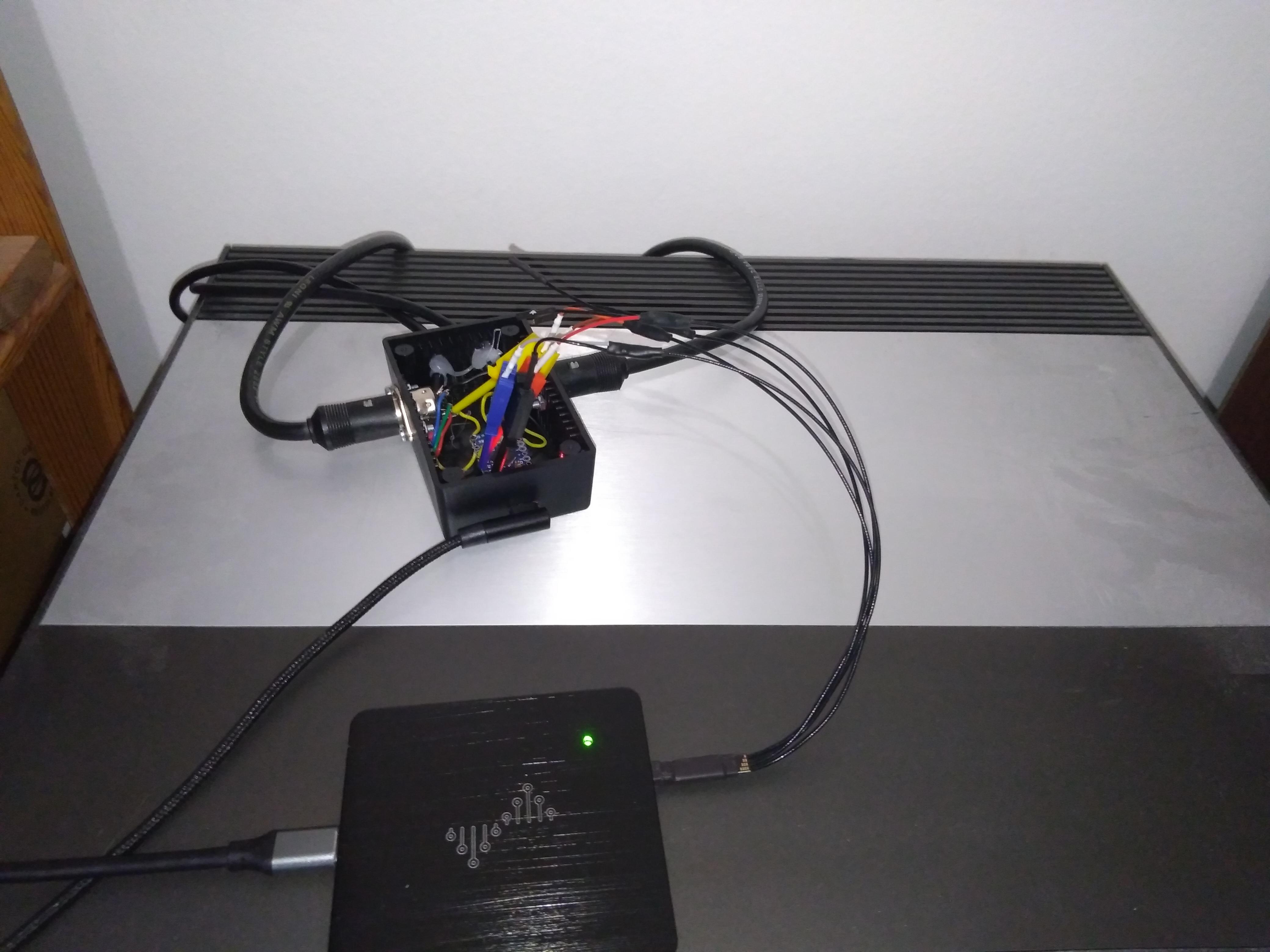
October 7, 2023 at 10:52 pm #24716Slowly reverse engineering the Datalink protocol used between the BeoMaster / BeoCord / BeoGram 5500, for a secret project.
 October 8, 2023 at 2:39 pm #24722
Keep us posted, we will not tell anyone!
October 8, 2023 at 7:28 pm #24723Slowly reverse engineering the Datalink protocol used between the BeoMaster / BeoCord / BeoGram 5500, for a secret project.

sounds very interesting. Looking forward to more info.
Are you avare of these two projects?:
October 9, 2023 at 10:05 am #24730Thank you for the links. I indeed had a look at them, but it turns out they are not comprehensive enough for my use case.
I will of course post my progress here, once I reach a point where I have enough to show to justify a dedicated thread.
October 9, 2023 at 1:15 pm #24734Finally getting round to sorting out my Beolab Penta 2s. I re-foamed the midranges earlier in the year so have now re-fitted them and am working on the amplifiers.
- AuthorPosts
- You must be logged in to reply to this topic.

