Beomaster 6000 Power-On Issue
Tagged: 6000 IC4
- This topic has 69 replies, 7 voices, and was last updated 2 years ago by
Glitch.
- AuthorPosts
- January 19, 2023 at 5:36 am #14618
OK, my fault for relying on my poor memory. I don’t have a BM6000 to try it on and I just remembered it as being like other products from that era which did use the 50/60Hz signal for power failure indication. It’s now more than 40 years since I last worked on the BM6000.
January 19, 2023 at 2:37 pm #14641The 50/60Hz signal is an example of the chicken/egg situation I was referring to earlier. It would be easy to interpret a missing square wave on the signal as the cause for the receiver not running. The lack of the signal could also be an effect of the CPU not setting up the I/O ports. The tricky part is figuring out if it is the cause or effect. In quattro’s case, my test provides a clue to what is going on. Another test that could be done is to add a pull-up resistor to +5v somewhere on the 50/60Hz signal circuit and verify that the signal works as expected.
Glitch
January 19, 2023 at 10:01 pm #14689Perhaps unrelated, but I noticed resistor R27 has been snipped out of my motor control board. Looks to be related to the volume control. Is this a factory thing, or should I install a 470 ohm resistor there? I noticed the resistor present in Sonovor’s thread, here.
Missing R27:
 January 19, 2023 at 10:20 pm #14690
One of my BM6000’s has R27 present, it is “cut out” in the other two.
I don’t think that anything related to the motor control will stop the receiver from initializing.
You mentioned that the motor runs continuously… This is usually caused by a dirty initial volume slider or the motor control trim pots being out of adjustment/corroded. I believe that you can perform the Preset Volume Adjustment from the service manual without the CPU being fully initialized. I know it would bug the heck out of me if the motor was constantly spinning while I was trying to debug the other issues.
Glitch
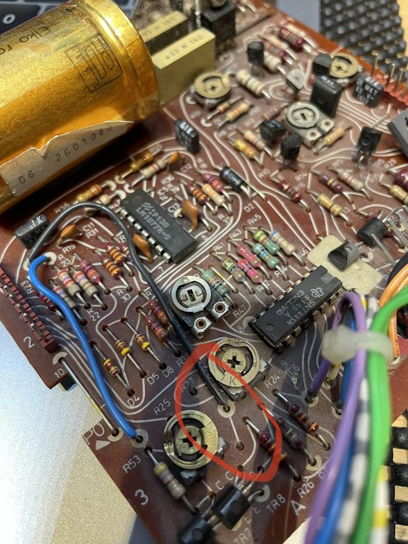
January 20, 2023 at 3:42 am #14697Adjusting R25 solved the motor always-on issue. The full calibration procedure requires the receiver to be on so the volume can be adjusted to various levels.
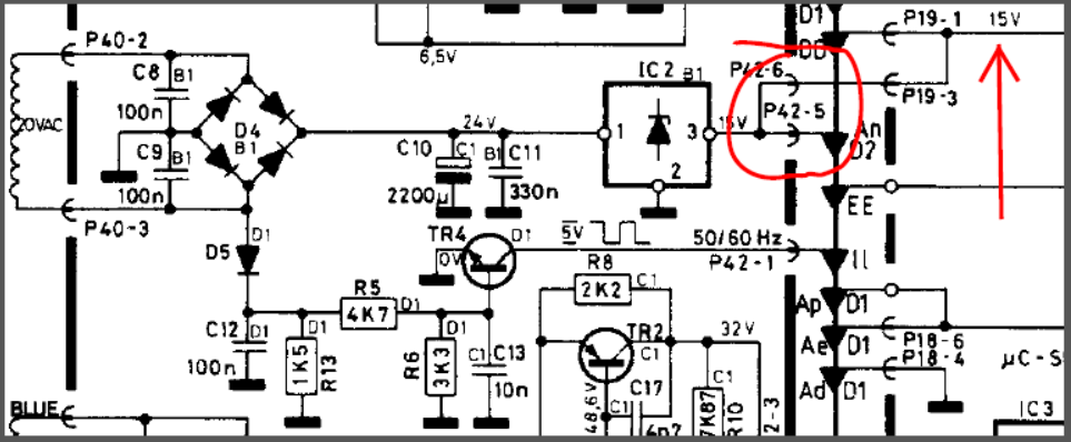
January 20, 2023 at 5:50 pm #14713I’m probably getting desperate, but would 14.7 volts here cause a problem? I know this 15v goes to the standby circuit amongst many other things. And I’m not getting 5V on Pin18 of the CPU (st.by), though i’m probably running into that chicken/egg problem again 🙂
I’m getting 14.7volts at pin 3 of IC2 (board 16).
 January 20, 2023 at 7:07 pm #14721
I understand that desperate feeling…
14.7v seems to be a bit low, but not so much that I would expect it to cause a problem.
It is a fully regulated voltage so I would expect it to be closer to 15.0v. A quick test to see is something is dragging it down would be to pull P42 and measure the voltage on pin P42-5. The relative difference between no-load and loaded is of most interest.
Glitch
January 20, 2023 at 7:24 pm #14723I had to go back and check my notes… There is a good chance that the Standby pin is setup/initialized at the same time as the 50/60Hz pin. So whatever is keeping one of them from working is likely keeping other ones from working.
Are you sure that BOTH +5v power supplies on the CPU board are close to 5v?
Glitch
January 20, 2023 at 9:50 pm #14742Same 14.7V on P42-5 with P42 wires pulled. Interestingly, I get “P” in the display when P42 is pulled. It never displayed anything before save for the colon, dot, and radio LEDs.
Definitely have both 5V supplies. I get a perfect 5V at the CPU pin 40 and the other ICs on board 2 are all getting 4.9v from the 2TR1 supply.
I am getting some sort of signal from the CPU’s 50/60Hz pin (16). The waveform looks exactly like your did on page one of this thread. Even has the same blip on the right side of the square.
January 21, 2023 at 3:39 am #14749Regarding the 14.7v instead of 15v… Check that the heat sink compound isn’t dried up. Otherwise, the regulator is likely just “off a bit”. Swapping it with a new one is a easy job and the part is commonly available (but probably isn’t needed).
I believe that the “P” display in this case just means that the CPU board is getting 6.5v to the LED displays, but the CPU isn’t pulling up the FAULT line. Getting a “P” is pretty easy. For example, there will be a “P” display if the CPU is removed. I think a “P” can also be an indication of a genuine fault in the main amp.
I mentioned the second 5v supply because it was the most recent cause of a “:.” display on my machine. I was testing pre-scalers chips and I bumped TR1 or TR2 and opened up a cold solder joint that killed the secondary 5v supply. I was pretty nervous for a while since I thought I might have damaged the CPU while swapping chips.
It is interesting that your 50/60 signal has the same blip. I’m not sure why this happens. I think I decreased my blip by changing 16TR4.
I’m not sure what to suggest next. Are you sure that you aren’t just “looking at it the wrong way”? Sometimes it seems that “looking at it the wrong way” is all it takes to break it. 😉
Let me know if there are any other signals that I can check on my working BM6000 for you to use as a reference. I should have one one of them on the bench in a few days to replace a burned-out bulb.
Glitch
January 21, 2023 at 7:37 pm #14783Thanks a lot for your help, Glitch. Hopefully I’m missing something obvious, will continue to work on it.
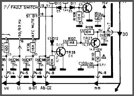
One final question, how does the “St.by” circuit work on board #2? Specifically around TR27. I know it gets 15V from board #6. I’ve got 15V at the DD (TR27 emitter) and 14.3V at the base, but then nothing on the collector (if I did, the relay would switch on). I’m guessing this tells me the CPU is not providing the necessary signal and TR28 is not pulling to ground? Thanks again!
 January 21, 2023 at 9:26 pm #14787
Hello Gentlemen, I fixed mine with the :. display! (Just now)
Story:
I was starting “my new to me” BM6000 (update to follow to Glitches help in my other post), and had no display but a . (stby dot)
I had a dead keyboard but the remote worked. When on, there was no frequency display, and the tuning indicator arrow>< showed and worked.
I decided to start a rebuild with the beoparts cap kit, and board 2 was a perfect start. It was 3 caps and a VR (R89) lower right on front of board 2.
I kept the board in place. Took a reading on the old VR and put the new one in with the same resistance setting.
Result: only got the :. and no remote or keyboard input brought it out of this state.
I rechecked all the connections and polarities – no change.
Then I read your post and although it is way over my head, there was the suggestion that a VR could be set wrong. Two tries on R89 – 30 degrees each move and it worked! It lit up in Standby (one dot) and the remote perfectly works.
I still have no keyboard working so here we go! any suggestions for the dead keyboard?
Regards
Terry
January 21, 2023 at 11:14 pm #14792I removed my response since I really didn’t answer the question. Hemenex’s reply below makes more sense.
Glitch
January 22, 2023 at 9:53 am #14797Sorry but if you have 15V at emitter TR27 and 14.3V at Base then TR27 as a PNP type should turn on. (0,7V on its BE-diode)
I would check TR27…
hx
January 22, 2023 at 10:07 pm #14841hi,
back at the beginning of this post
spassmaker wrote:
Hi The Strobe issue on the BM 8000 was just a misaligned Pot R15 which has to be adjusted to minimum ~3.6 Volt, the Pot was turned the whole way down and the CPU did not recorgnized the too small signal below 3,6 Volt. This Pot is not present in the BM 6000.On my BM6000, I had the :. also. (same symptoms)
Did you try VR 2R89 and adjust it? When I did yesterday on mine it worked as before the :. was gone and the . was there, It was not shut down and frozen now.
The VR was set wrong when I replaced it, and once adjusted the display and whole unit was in standby and able to work with the remote in all functions.
January 23, 2023 at 5:21 pm #14874Sorry but if you have 15V at emitter TR27 and 14.3V at Base then TR27 as a PNP type should turn on. (0,7V on its BE-diode) I would check TR27… hx
TR27 tests fine on the transistor tester, nonetheless, i swapped it out for another one. Same thing, nothing on the collector. In any case, this is probably secondary, as the relay should not be switched on in standby mode.
February 17, 2023 at 12:32 am #16009quattttro: Have you made any more progress?
I revisited my BM6000 that doesn’t power-up properly. I was able get it to work with a known working good CPU from another BM6000. Now I’m very confident that the original CPU is bad. With the bad CPU, I observe two different (pseudo-random) behaviors when I plug-in the receiver. The first is a “:.” display, the second is a “.” display with the main amp rail relay kicking in.
Glitch
February 19, 2023 at 5:33 pm #16187quattttro: Have you made any more progress? I revisited my BM6000 that doesn’t power-up properly. I was able get it to work with a known working good CPU from another BM6000. Now I’m very confident that the original CPU is bad. With the bad CPU, I observe two different (pseudo-random) behaviours when I plug-in the receiver. The first is a “:.” display, the second is a “.” display with the main amp rail relay kicking in. Glitch
No progress. Sits on my workbench, haunting me. I’m pretty sure mine has the same problem though, a faulty CPU. It is consistently unresponsive “.:”, & the main amp relay never kicks on unless I mess with the startup timing. Shame to turn it into a parts unit, but not much choice.
February 21, 2023 at 5:21 am #16306If anyone with a faulty Beomaster 6000 CPU is interested I have two unused CPUs, with no way of checking whether they are working or not. They have never been installed, but are original production samples. They have the same B&O item number, 8340285, but different dates, 8107 and 8138. I don’t know if any changes were made between those two dates, but presumably there were.
For anyone with the means, ability, and interest in rewriting the original program I also have a piggyback version of the 3870 processor with a socket for a 2716 EPROM on its back. There’s also a 2716 EPROM, but I don’t know if that contains a version of the BM6000 program or not, and no longer have the capability to read it.
February 21, 2023 at 2:49 pm #16320I might be interested in the CPU(s). It is not clear to me what you mean by “rewriting the original program”. Can you elaborate more about what you were thinking?
I’ve already started a project to re-CPU my broken BM6000. I’ve built a rough prototype with a modern CPU. I’ve written software to perform the basic functionality (i.e. buttons, displays, volume, FM, etc.). This software also includes main board debug capability. I was working on adding remote control communication and Datalink communication when I got sidetracked by other projects.
I then got another “parts” BM6000 which had a broken volume motor. I scavenged the motor from the BM6000 with the bad CPU to fix the “parts” machine. This pushed my re-CPU project from the back-burner to off-the-stove.
Re-CPU-ing the receiver opens up many possibilities to integrate the BeoSystem 6000 with modern audio networks. I have a dozen or so ideas so far. I have even implemented a couple of them on my prototype setup. I hope to get back to this project someday. I’ll need to find a replacement volume motor to make my prototype bench viable again. Do you happen to have a spare volume motor?
I’ve also been toying around with a more ambitious BM6000 project than the re-CPU one. I wouldn’t need a volume motor for this, but it would take significantly more resources to complete.
Glitch
- AuthorPosts
- You must be logged in to reply to this topic.
