BeoLab 8000: request for very first version of the Service Manual
- This topic has 3 replies, 3 voices, and was last updated 1 year, 8 months ago by
KolfMAKER.
- AuthorPosts
- June 6, 2023 at 2:42 pm #21095
Question:
Does anyone have a copy of the very first version (Mark 1) of the service manual for the Beolab 8000?
- The Service Manual on Beoworld is Mark 2.
- The type numbers did not change between Mark 1 and 2 so the front cover numbers are the same.
- One must look at the circuit to see the difference.
- My BeoLab 8000 has serial number 1448 8372, and is a type 6801.
Background
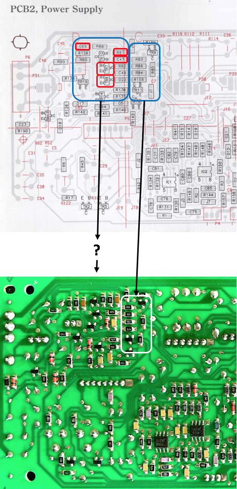
I have an issue with a BeoLab 8000. Using the circuit diagram in the service manual, I found out there was a difference between the diagram in the service manual, and the layout of the PCB of the BeoLab 8000 I have with a repair issue.
The images below show some of the differences:
- The top image shows the diagram from the Service Manual I have from the BeoWorld forum.
- The lower image shows a picture (from the same section) of the PCB of the BeoLab 8000, for which I have to solve an issue.
- Comparing the diagram to the physical board, I found that the the five components marked red (in the left blue square), can’t be found in the same section on the PCB (lower image). Or at least, it just looks different which makes it difficult to understand what is what.
 June 6, 2023 at 6:30 pm #21107
The SM I have has the same component layout as yours.
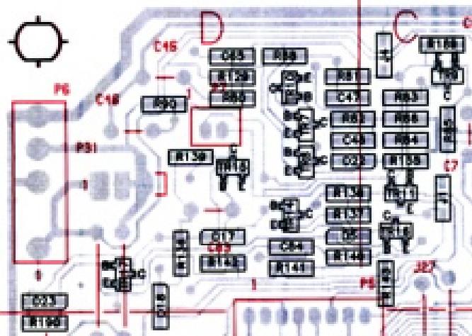
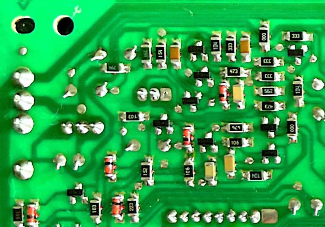
June 7, 2023 at 8:55 am #21125If you expand the physical board layout and the drawing you see that the printed circuit track layout is quite different in the area of concern.

 June 7, 2023 at 3:55 pm #21136
Thnx for this addition Keith.
You are right: the tracks are different, components are in different locations or positioned in a different direction, …
I hope someone has the right version of the service manual, with a diagram reflecting the pcb in the photo picture.
- AuthorPosts
- You must be logged in to reply to this topic.
