Beolab 5000 Type 5303
Tagged: Beolab 5000 Type 5303
- This topic has 8 replies, 3 voices, and was last updated 2 years, 9 months ago by
Pindsen.
- AuthorPosts
- May 1, 2022 at 7:47 pm #4622
Hi,
I’m trying to replace bulbs in a Beolab 5000 amplifier but cannot see how I get to them. I have dissembled the front so that I now can see the black front behind the alu. front but I am not able to turn the power bulb out (my fingers are too big). The Stereo bulb is behind the black front and unscrewing the four countersunk screws in both sides do not release the black front. How do I get properly to these two bulbs?
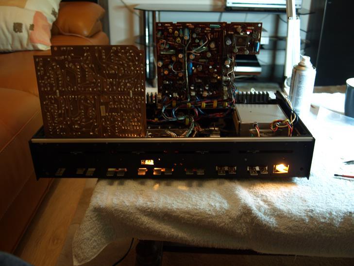
/PindsenMay 2, 2022 at 8:55 am #4625You need to take the top off, remove the screws holding the amp PC down….it’s on a hinge so will lift up and can be put into the service position which is vertical. This allows access to the power on bulb, its a push fit onto a tab and can ce carefully pulled backwards untill released, you can then unscrew the lamp and replace it…..make sure you use the propper voltage…I think its 60vdc
 May 2, 2022 at 8:56 am #4626
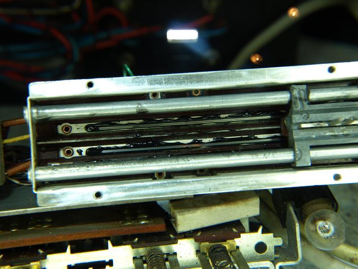
This is a pic showing the lamp still on the push fit tab
 May 2, 2022 at 9:24 pm #4639
Hi,
Yes of cause, now I get it 🙂
Then I have three more questions:- When I apply a line signal to TAPE I have sound in speakers, but when I apply the same line signal to either the TUNER or AUX there are no sound. I have tried to follow the schematic but it just a lot of switches – any idea?
- There are adjust knobs in the bottom and also High/Low switches – It is mentioned in the service manual but I can’t find how to adjust the knobs, is it just by ear? – any idea?
- I have low light in the bulbs and at test point BP I only measure 25,5V (60V is expected). I have tried to turn the potentiometer 457 but no change, it is steady at 25,5V. Before moving on I would to hear any ideas?
/Pindsen
May 3, 2022 at 8:54 am #4650Ok……one thing at a time.
- For some strange reason the internal wiring which connects the AUX signal DIN to the amp is wired differently to the TAPE input DIN, I found this out the hard way. Connect your signal to the phono plugs instead of the DIN connector for the AUX input and see if you then get sound to your speakers.
- The Hi and Lo s are latching switches that need to be pushed forwards to engage or disengage….these are used if your input needs to go through the pre amp stage or not…a low signal will need to (I think this is right…..). The + and – trim pots can be set by ear….they adjust the volume of each speaker to balance the sound.
- I will need more info for this question….and maybe some pics?
May 3, 2022 at 9:06 pm #4694Hi again.
Thanx for helping. You where right regarding using the phono plugs, then there are sound using the Tuner and AUX input.Regarding the power supply issue the 33V part is OK but the 60V is wrong. I have found that component 471 (SE8002) is shorted between B-C (4 ohm). I am not able to find a SE8002 but according to this old post a 2N2102 should do the job:
https://archivedforum.beoworld.co.uk/forums/p/40097/335005.aspx#335005/Pindsen
May 4, 2022 at 12:46 am #4701BC141 should be OK too
May 4, 2022 at 7:15 am #4705I would also replace ZF18 Zener diode….check the other transistors around the voltage regulator too…..something caused may have caused the SE8002 to short out.
Craig
May 27, 2022 at 8:20 pm #5358I have replaced the SE8002 with a BC141-10 and it works fine. I had then 62V at BP testpoint and trimmed it to approx. 60V.
Only downside now is that it gives a high pop in the speakers when they are coupled in./Pindsen
- AuthorPosts
- You must be logged in to reply to this topic.
