Beogram 8002 repair – reset circuit?
- This topic has 5 replies, 3 voices, and was last updated 1 year, 9 months ago by
premiumverum.
- AuthorPosts
- May 31, 2023 at 4:32 pm #20935
Hi all,
My BG8002 has died. When plugged in there is no response, no standby dot.
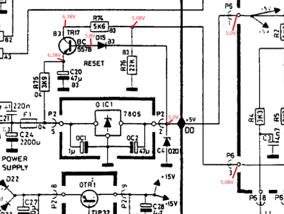
F1 was blown, D20 short circuited and blackened the PCB. I replaced both and got the +5v back on P6-1 .However still no response, no standby dot. Due to the damage to D20 I suspected the reset circuit. P6-3 measures +5V, which I think means the reset is active so the turntable wont start up. I checked TR17 on my HFE meter, it had HFE 0 so I replaced it with a new BC557B. However still no response. The three resistors R74,75,76 measure within spec.
First question before I dig deeper: am I correct that the reset circuit is now active and should have 0V on P6-3?
June 1, 2023 at 7:36 am #20955Hi
First, F1 is blown because D20 was shot.
D20 is a protection Z diode wich makes a short circurit to ground when the voltage rises above e.g. 6,3 volt to protect the uPC.
I’m not really sure but for me it looks like the reset IC1 PIN39 should have low level.
I would recheck TR17 and C20 and D15.
Maybe member Dillen has a suggestion about the reset state at IC1.
BTW:
Did you recap the Beogram or did you resolder the solderjoints of all plugs so far?
Lot of trouble comes from these failured caps and dry solderjoints.
Kind regards
Christian
June 1, 2023 at 11:47 am #20963Thanks Christian.
The BG was recapped 5-10 years ago and any suspect joints were reflowed then. Could of course be a new crack somewhere, I hope not.
Your explanation helps me understand the problem. I am not schooled in electronics but the B&O hobby is teaching me step by step. The function of the zener has made my comprehension of the circuit more clear.
June 2, 2023 at 3:13 pm #21016OK, replaced D15 with a new 1N4148. No change!
I measured around in the circuit again and read up on using the BC557B as a switch. The 3 resistors are within spec.

Assuming I understand correctly: as the BC557B is PNP, making the base low (0V) should close the switch activiting the reset pin with 5,08V. However, for some reason there is 5,8V on the base. Yet the switch seems closed because C and E measure the same. Why is there 5,8V on the base, why is the switch closed with a positive voltage on the base? Maybe C20 is the cause but I can’t see how?
June 2, 2023 at 3:26 pm #21018TR17 C-E short?
Martin
June 2, 2023 at 6:32 pm #21023Checked C-E for continuitiy with the multimeter – nothing. I desoldered TR17, it gave a HFE reading of 381, seems normal.
I’m not sure what to do next. Maybe try another bc557b, maybe I got a dud? I could replace C20, unforunately I have no capacitance tester and no 47 uF cap on hand. I’ll have to go to the shop first anyway.
- AuthorPosts
- You must be logged in to reply to this topic.
